Plans
Construction of a Tesla High-Frequency Apparatus
Many requests are received for information on the construction of a Tesla coil and transformer to go with it. As this requires specific directions of some length we believe it advisable to reprint the article by Mr. H. L. Transtrom which appeared in the January, 1909, issue of Popular Electricity.
This article contains all the information necessary to construct a coil and transformer with which to perform the usual high frequency experiments such as lighting a sixteen candle-power lamp one terminal of which is held in the hand and the other connected to one terminal of the Tesla coil, the production of fantastic brush discharges, the melting of fine wire by high frequency current passed through the body, lighting of a vacuum tube, etc. The outfit may also be used for medical work and wireless telegraphy. Following is a description of the apparatus:

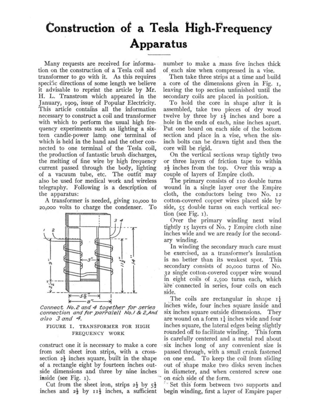
A transformer is needed, giving 10,000 to 20,000 volts to charge the condenser. To construct one it is necessary to make a core from soft sheet iron strips, with a cross-section 2 inches square, built in the shape of a rectangle eight by fourteen inches outside dimensions and three by nine inches inside (see Fig. 1).
Cut from the sheet iron, strips 2 1/2 by 5 1/2 inches and 2 1/2 by 11 1/2 inches, a sufficient number to make a mass five inches thick of each size when compressed in a vise.
Then take three strips at a time and build a core of the dimensions given in Fig. 1, leaving the top section unfinished until the secondary coils are placed in position.
To hold the core in shape after it is assembled, take two pieces of dry wood twelve by three by 1 inches and bore a hole in the ends of each, nine inches apart. Put one board on each side of the bottom section and place in a vise, when the six-inch bolts can be drawn tight and then the core will be rigid.
On the vertical sections wrap tightly two or three layers of friction tape to within 2 1/2 inches from the top. Over this wrap a couple of layers of Empire cloth.
The primary consists of 110 double turns wound in a single layer over the Empire cloth, the conductors being two No. 12 cotton-covered copper wires placed side by side, 55 double turns on each vertical section (see Fig. 1).
Over the primary winding next wind tightly 15 layers of No. 7 Empire cloth nine inches wide and we are ready for the secondary winding.
In winding the secondary much care must be exercised, as a transformer's insulation is no better than its weakest spot. This secondary consists of 20,000 turns of No. 32 single cotton-covered copper wire wound in eight coils of 2,500 turns each, which are connected in series, four coils on each side.
The coils are rectangular in shape 1 1/4 inches wide, four inches square inside and six inches square outside dimensions. They are wound on a form 1 1/4 inches wide and four inches square, the lateral edges being slightly rounded off to facilitate winding. This form is carefully centered and a metal rod about six inches long of any convenient size is passed through, with a small crank fastened on one end. To keep the coil from sliding out of shape make two disks seven inches in diameter, and when centered screw one on each side of the form.
Set this form between two supports and begin winding, first a layer of Empire paper and then a layer of wire alternately, until the 2,500 turns are on. It will be found very easy to wind this fine wire in layers if it is allowed to slide over a rod a foot or so away and guided with one hand while winding with the other. Leave a margin of 1/4 inch in each layer.
All coils should be tested to see if there are any bare places or if the wire is in one continuous piece. If not, do not attempt to use it as it will surely burn out when run a short time. When all coils are completed they should be dried in an oven, not too hot, and then laid flat in hot petroleum and boiled for several hours, and then left to cool in the mixture until set, which will take quite a long time.
When thoroughly cold, take carefully out of the mixture and after taking the surplus off the coils, assemble on the core over the primary, four on each side. To keep the coils insulated from each other, cut 36 squares of Empire cloth seven by seven inches and cut out of their centres a hole that will fit snugly over the Empire cloth on the primary. Use six thicknesses between adjacent coils, there being only six places to use these separators.
The coils should all be connected in series as though it were one continuous wire beginning at the top of one section and ending at the top of the other. (See Fig. 1.)
Connect all coils so that they have the same relation to one another as the turns in the primary. Keep the coils one inch from the bottom of the core by inserting narrow strips of birch wood across the binding boards and cover with several thicknesses of Empire cloth.
When all the coils are assembled and connected properly, the top part of the core may be completed. A sheet of micanite nine by four by 0.1 inches should be used to separate the vertical sets of coils. Make a box of close-grained hardwood seven by fifteen by fourteen inches inside measurements and coat thoroughly with hot paraffine to make it perfectly tight.
When the transformer is set in the box it may be fastened by screws to the bottom binding boards.
Bring the ends of the primary wires to one side of the box and the secondary to the other side where they can be connected to proper binding posts. The secondary wire should be kept clear from the core and be led out through hard rubber rod binding posts. The four primary wires should be arranged so that they can be easily connected either in series or parallel.
Boil 40 pounds of extra amber petroleum and fill the box to the top and screw fast the cover and the transformer is complete.
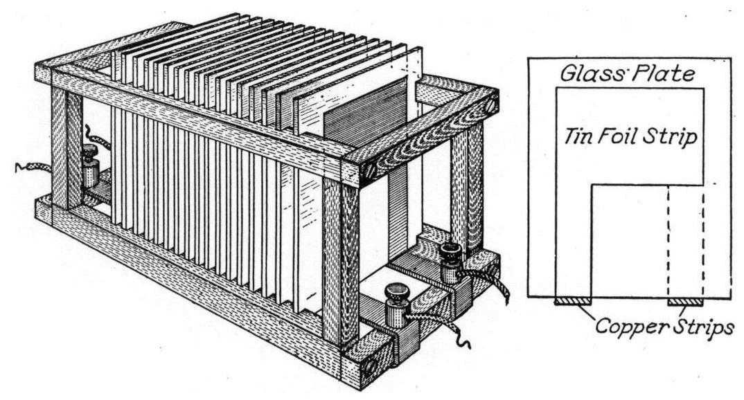
Next we construct an adjustable condenser of seventeen plates of double thickness window glass ten by twelve inches. Coat all the plates with tin foil five by six inches on both sides. Leave a margin of two inches on top and sides and five inches on the bottom. On eight of these plates paste a strip of tin foil on the lower right hand corner to reach the bottom and on the other nine paste them on the lower left hand corner of the foil. These are the connectors which rest on two copper strips laid parallel four inches apart on the bottom of the crate with binding posts on each end. The strips are fastened on and insulated from the bottom of the wooden crate, with slots in the sides to receive the plates. (See Fig. 2.)
The Tesla coil consists of a primary of seven turns of No. 6 bare copper wire and a secondary of 180 turns of No. 22 bare copper wire wound in a single layer on a drum six inches in diameter and fourteen inches long made of dry birch boards glued together in a circle and then turned off in a lathe. The turns of wire are carefully spaced apart 1-16 inch when winding, leaving a margin of 1/2 inch on the ends. The primary is wound on a wooden drum eight inches in diameter and 4 1/2 inches long, the turns being carefully spaced apart and fastened. The secondary coil is set on top of the primary coil and the base fastened to the bottom drum.
Give the secondary winding a coat of orange shellac, being careful not to disturb the turns while doing so. A nice turned top can be added for appearance, and a brass rod four inches long and 3/8 inch thick driven tightly in the centre of the top and well rounded off, will be the discharge rod, being connected to the top end of the secondary wire.
The lower end of the secondary terminates in another binding post.
On the primary a binding post is fitted at only the upper end, while the other connection is a sliding contact.
For a spark gap take a glass jar about six inches in diameter and eight or ten inches in height and make a hole in the bottom 1/4 inch in diameter. To do this take clay or putty and lay a thick layer over the centre of the bottom of the jar. Make a 1/4-inch hole in the clay down to the glass and fill with hot solder. The glass will fall out the shape of the hole in the putty or clay.
Make a cover from some nice hardwood to fit tightly in the top of the jar, and bore a hole in the centre, in which fasten securely a threaded 1/4-inch nut which is connected by a wire to a binding post on one edge of the cover.
A 1/4-inch rod threaded the whole length is fitted with a hard rubber handle 3/4 by three inches long. This is screwed in the threaded nut. The length of rod depends on the height of jar used. Another rod is fitted with a metal ball 3/4 inch in diameter and inserted in the hole in the bottom and then through a base of hardwood on which a binding post is placed.
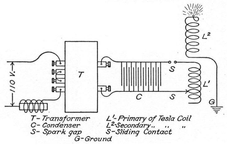
Now to operate the completed apparatus connect as per diagram, Fig. 3.
Connect the lower terminal of the secondary of the Tesla coil to a good ground with stranded wire, as a stranded wire is a better conductor for high frequency currents than is solid wire.
Although good results can be obtained by using the primary in parallel on 110 volts, 60 cycles, consequently 20,000 volts secondary voltage, yet as good results with better control may be had by using the primary sections in series and an adjustable choke coil in series with them. The choke coil can be made from a mass of sheet iron 2 by 2 by eight inches, which is inserted in a hollow coil of No. 10 copper wire of 110 turns.
By inserting the core in the coil the current can be varied according to the depth inserted. This outfit is for the uni-polar or single pole method of generating high frequency currents. If all connections are correctly made the spark gap should be turned until the spark will just jump easily, then on the primary of the Tesla coil move the sliding contact on the second turn from the top, then onto the next turn and so on until the desired results are obtained.
To light a lamp use the fourth or fifth turn and slide the lamp along the side until the brightest light is obtained.
Always disconnect the primary of the transformer before attempting to adjust the different parts.
By adding condenser plates or taking them out of the crate, one by one, the coils will be brought in tune under certain conditions.