Nikola Tesla Articles
Analysis of a Classical Tesla Coil
Introduction
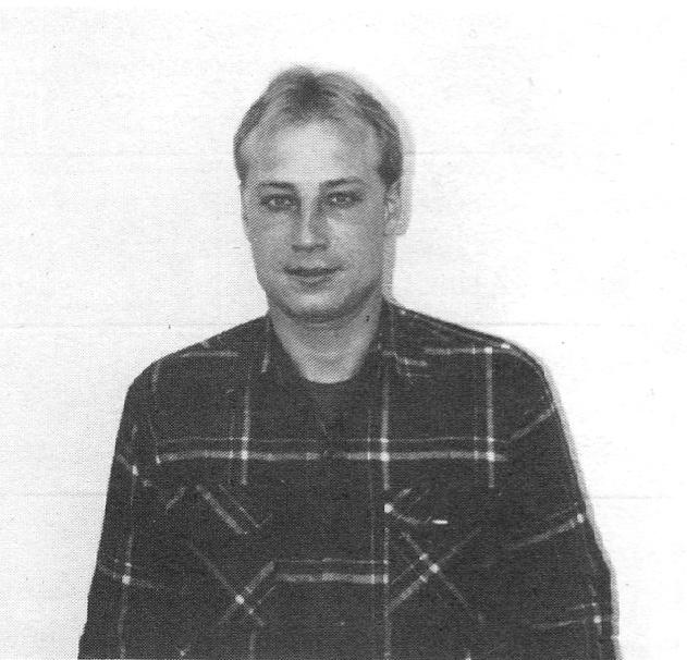
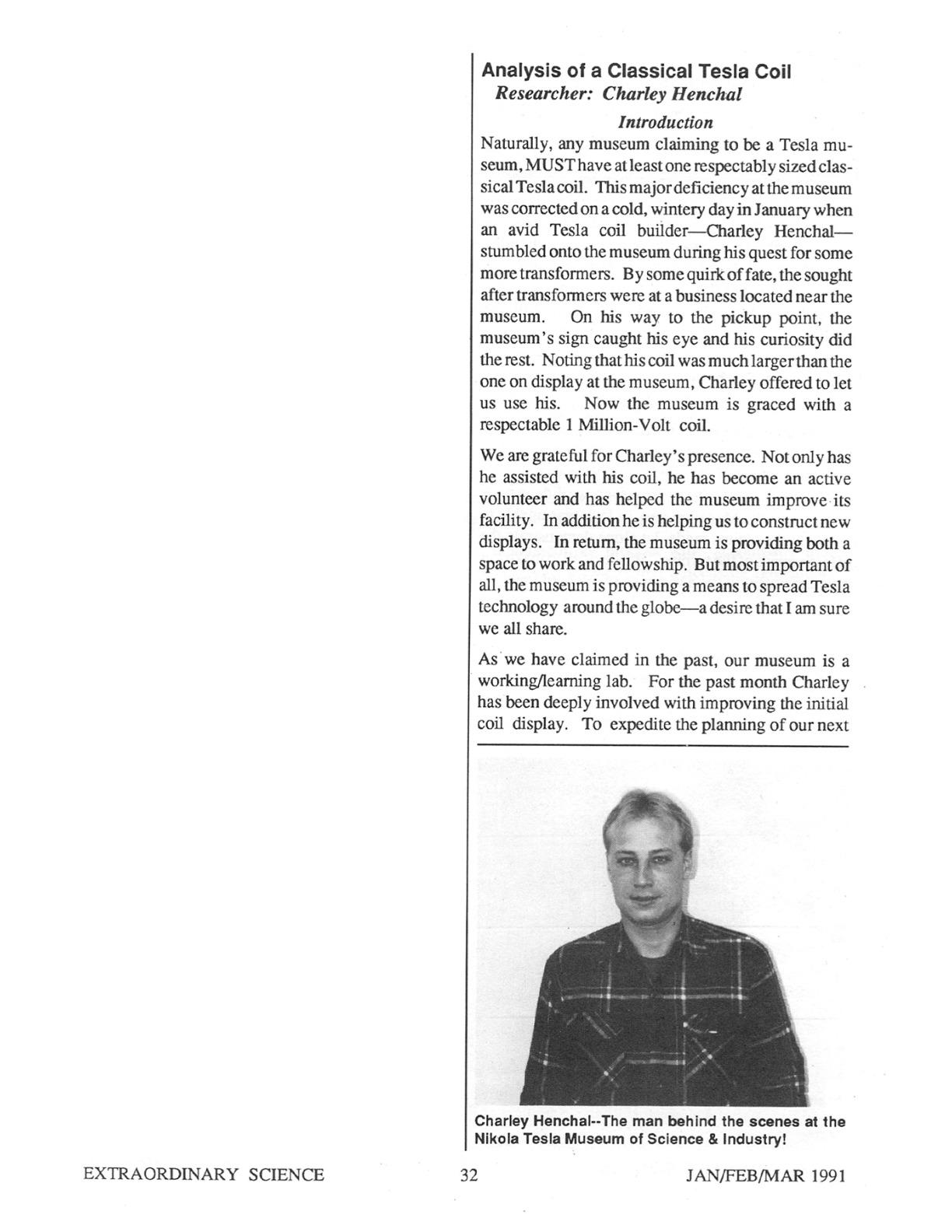
Naturally, any museum claiming to be a Tesla museum, MUST have at least one respectably sized classical Tesla coil. This major deficiency at the museum was corrected on a cold, wintery day in January when an avid Tesla coil builder - Charley Henchal - stumbled onto the museum during his quest for some more transformers. By some quirk of fate, the sought after transformers were at a business located near the museum. On his way to the pickup point, the museum’s sign caught his eye and his curiosity did the rest. Noting that his coil was much larger than the one on display at the museum, Charley offered to let us use his. Now the museum is graced with a respectable 1 Million-Volt coil.
We are grateful for Charley’s presence. Not only has he assisted with his coil, he has become an active volunteer and has helped the museum improve its facility. In addition he is helping us to construct new displays. In return, the museum is providing both a space to work and fellowship. But most important of all, the museum is providing a means to spread Tesla technology around the globe - a desire that I am sure we all share.
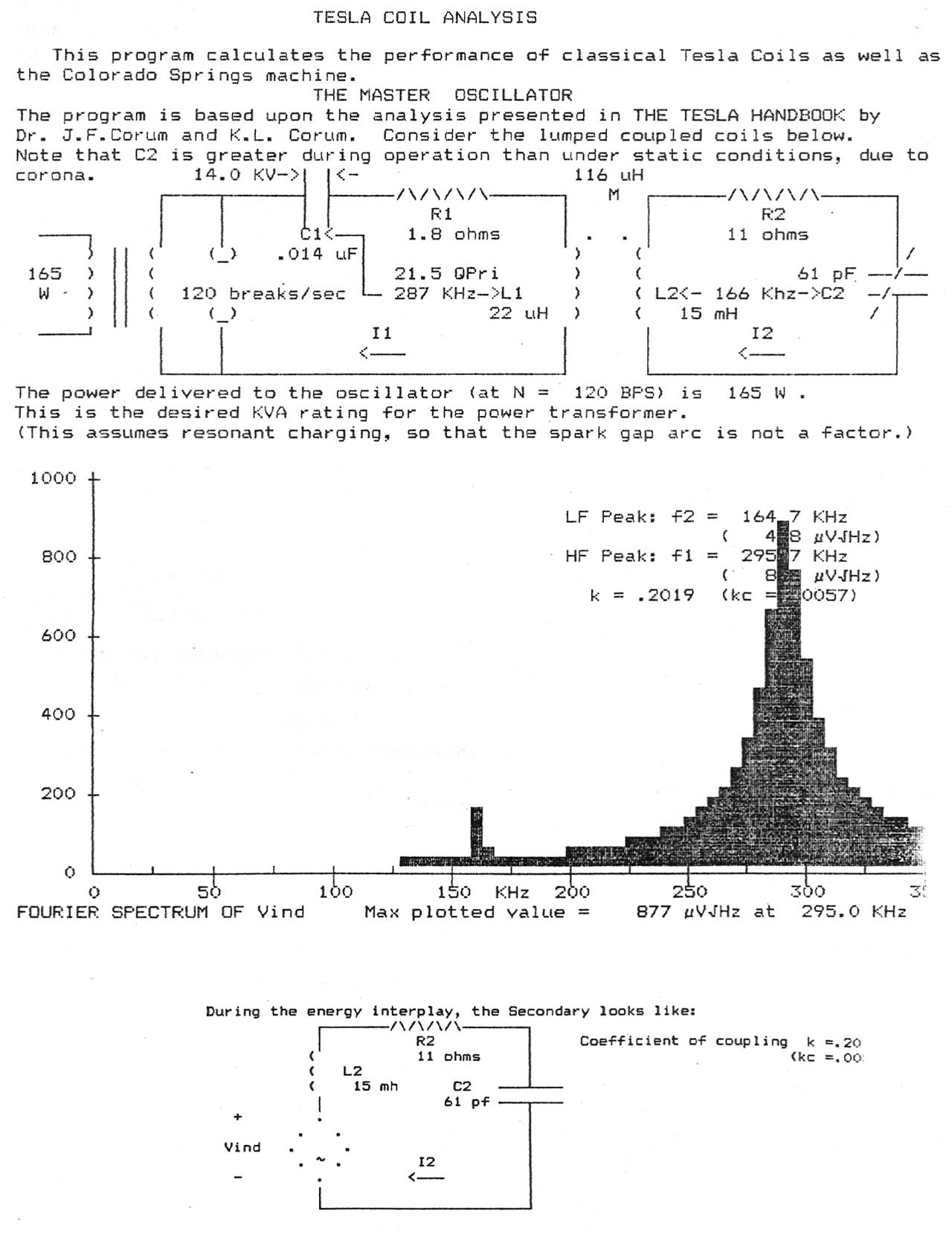
As we have claimed in the past, our museum is a working/learning lab. For the past month Charley has been deeply involved with improving the initial coil display. To expedite the planning of our next large coil, Charley and I have been working on a computer analysis of the coil using TCTutor - a program written by Corum & Associates for Tesla coil analysis on an IBM Personal Computer. This experience has taught bot Charley and myself quite a bit about how to obtain measurements of the parameters needed for an analysis of the coil.
The Primary Circuit
The first parameter required by TCTutor was the primary’s inductance (L1). The inductance was measured by disconnecting the primary coil from the rest of the circuit and then took a reading off an LCR meter which was connected across the coil. We used an Elenco LCR-1801 meter. We measured 22uH. Charley had calculated it to be 19uH - a difference of only 16%.
The primary’s capacitance (C1) was required next. This measurement is also a fairly straightforward measurement to make, in that all that is necessary is that the LCR meter is placed across the plates of the capacitor - the capacitor is also disconnected from the rest of the circuit. We measured 0.014uF (which happens to the sum total of 24 bottles).
The resistance of the primary circuit (R1), although small, is another necessary parameter. We are unsure whether we used the proper technique for obtaining this parameter. We connected the entire primary circuit together, adjusted the gaps so that the points touched each other, and then took a reading. We measured 1.84 ohms. Tesla had designed a superconducting coil which would reduce the primary resistance (loss) as low as possible.
Being that Charley currently has an air gap, we have no real control over the spark gap break timing. Tesla commented that the one area that could bring a magnitude of improvement to a coil’s performance was an improved spark gap. For this project’s purposes, we use the figure of 120 breaks per second. This figure was mentioned in the Tesla Handbook by JH Couture as being proper for air gap discharges.
The Coil Interface
The parameter that kind of had us stumped was the mutual inductance. Fortunately for us, the Tesla Handbook once again came to our rescue. By shorting the top of the secondary and measuring the primary’s inductance (LSHORT) and then by opening the secondary and once again measuring the primary’s inductance (LOPEN), we were able to determine k.
$! {k = \sqrt{1 - \left({L_{SHORT} / L_{OPEN}}\right)}} $!
Once k was determined, we then measured the secondary’s inductance (L2) in a manner similar to that of measuring the primary’s inductance. The values thus obtained were plugged it into the following formula to calculate mutual inductance M.
$! {M = k\sqrt{L1/L2}} $!
The Secondary
We then started our analysis of the secondary coil. The secondary’s inductance (L2) was measured previously to determine mutual inductance. We used the previous measurement.
The secondary self-capacitance (C2) was (and still is) a tough nut to crack. We consulted with Dr. Corum, who graciously supplied us with the information to measure the self-capacitance. The information is contained in the Radio Engineer’s Handbook (1943) by Frederick Emmons Terman, ScD. Due to a lack of the necessary equipment, we ended up calculating the secondary capacitance with a formula we fortuitously discovered in Tesla Handbook:
C2 = 109/(39.5 Fr2L2)
Needless to say, measuring the final parameter - secondary resistance (R2) - was sort of anticlimactic.
The Analysis
The measurements were plugged into TCTutor for analysis. It churned out the coil’s characteristics on a schematic diagram - as a bonus the program performs an analysis in both the frequency and time domains. TCTutor’s analysis is on the following page.
Since undergoing this ordeal, we have decided to write an IBM compatible program for Tesla Coil design based on the Tesla Handbook - an excellent resource that has helped us more than once during this exercise. We will then test it out by building a 5-Million Volt coil for the museum. If all goes well, we should be able to publish the results in the next issue and demonstrate it at the upcoming Extraordinary Science Conference in July.