Nikola Tesla Books
Books written by or about Nikola Tesla

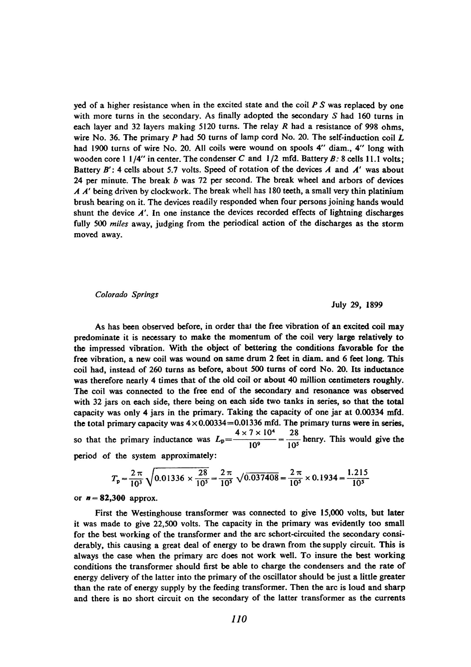
yed of a higher resistance when in the excited state and the coil P S was replaced by one with more turns in the secondary. As finally adopted the secondary S had 160 turns in each layer and 32 layers making 5120 turns. The relay R had a resistance of 998 ohms, wire No. 36. The primary P had 50 turns of lamp cord No. 20. The self-induction coil L had 1900 turns of wire No. 20. All coils were wound on spools 4" diam., 4" long with wooden core 1 1/4" in center. The condenser C and 1/2 mfd. Battery B: 8 cells 11.1 volts; Battery B’: 4 cells about 5.7 volts. Speed of rotation of the devices A and A’ was about 24 per minute. The break b was 72 per second. The break wheel and arbors of devices A A’ being driven by clockwork. The break whell has 180 teeth, a small very thin platinium brush bearing on it. The devices readily responded when four persons joining hands would shunt the device A’. In one instance the devices recorded effects of lightning discharges fully 500 miles away, judging from the periodical action of the discharges as the storm moved away.
Colorado Springs
July 29, 1899
As has been observed before, in order that the free vibration of an excited coil may predominate it is necessary to make the momentum of the coil very large relatively to the impressed vibration. With the object of bettering the conditions favorable for the free vibration, a new coil was wound on same drum 2 feet in diam. and 6 feet long. This coil had, instead of 260 turns as before, about 500 turns of cord No. 20. Its inductance was therefore nearly 4 times that of the old coil or about 40 million centimeters roughly. The coil was connected to the free end of the secondary and resonance was observed with 32 jars on each side, there being on each side two tanks in series, so that the total capacity was only 4 jars in the primary. Taking the capacity of one jar at 0.00334 mfd. the total primary capacity was 4 x 0.00334 = 0.01336 mfd. The primary turns were in series, so that the primary inductance was $! {L_{p} = {{4 \times 7 \times 10^{4}} \over 10^{9}} = {28 \over 10^{5}}} $! henry. This would give the period of the system approximately:
$! {T_{p} = {{2 \pi \over 10^{3}} \sqrt{0.01336 \times {28 \over 10^{5}}}} = {{2 \pi \over 10^{5}} \sqrt{0.037408}} = {{2 \pi \over 10^{5}} \times 0.1934} = {1.215 \over 10^{5}}} $!
or n=82,300 approx.
First the Westinghouse transformer was connected to give 15,000 volts, but later it was made to give 22,500 volts. The capacity in the primary was evidently too small for the best working of the transformer and the arc schort-circuited the secondary considerably, this causing a great deal of energy to be drawn from the supply circuit. This is always the case when the primary arc does not work well. To insure the best working conditions the transformer should first be able to charge the condensers and the rate of energy delivery of the latter into the primary of the oscillator should be just a little greater than the rate of energy supply by the feeding transformer. Then the arc is loud and sharp and there is no short circuit on the secondary of the latter transformer as the currents
110
July 28
This entry provides one of the most detailed descriptions of the receiver with two rotating coherers and a condenser for accumulating the energy from weak signals. At point b the circuit C - P is periodically made and broken and the resulting AC pulses bias sensitive device A' in the secondary. Sensitive device A is still poorly conducting so the charging current of C via damping coil L is small. When an arriving electromagnetic wave reduces the resistance of A, C charges much faster and the voltage induced in secondary S also rises rapidly. The resistance of A' drops rapidly and current from battery B' activates relay R. Judging by Tesla's report, the receiver was very sensitive to distant electrical discharges.
July 28
This is one of the most detailed descriptions of a receiver with two rotating sensitive devices and capacitor for effective accumulation of weak signals. At location 'b' the circuit C - P is periodically switched on and interrupted and obtained alternating current impulses pre-excite the sensitive device A' in the secondary. In the non-excited state, other sensitive device A has high resistance* and therefore the charging current C via ballast coil L is low. When the resistance of sensitive device A reduces, due to action of electromagnetic waves, capacitor charging current C quickly increases and the induced voltage in secondary S is quickly increased as well.
Sensitive device A' resistance is quickly reduced, and current from battery B' acts on relay R which is activated.
Judging on the basis of what Tesla displays, the receiver is very sensitive and reacts to remote electrical discharges.
July 29
To check out his theoretical conclusions about the free oscillation of the “extra coil” (see 30 June and 26 July) Tesla made a new coil with a higher inductance. As this was his first experiment with the new coil, he had to adjust the circuit parameters by trial and error.
Tesla's ingenuity found full expression in the way in which he developed condensers for high voltages. He filed a patent application on his design for a fluid electrolyte condenser on June 17th 1896(67).
July 29
For the purpose of theoretical conclusions of "additional coil", free vibrations checking (please see June 30 and July 26) Tesla constructs a new coil with higher inductance than previously. With this new ''additional coil'' he puts the oscillator in operation. As he used to do it, he weighs the inductance in primary circuit (means of regulating coil) and numcer of jars (i.e. capacitance) so as to obtain the maximum voltage in the secondary. The rough estimate of operating frequency obtained on the basis of inductance and capacitance in the primary.
When adjusting arcing device (please see July 27) he observes that the bulb on the network supply feeder gives a brighter light when there is no spark on the arcing device. He is not sure whether the reason is capacitive loading of the Westinghouse transformer (network transformer) which could cause a resonant overvoltage. He suspects "electrostatic action" and gives his opinion on that phenomenon.
During the process of looking for the conditions for best oscillator operations, Tesla checks the circuit parameters. He matches the primary capacitance according to supply transformer power. By capacitance increase in the primary he provides a larger energy transfer, but the best results are obtained when the system operates at suitable frequency. The operating system he applies here could be named "test and guessing method", which is understandable with regards to his first experiments with new "additional coil".
"Additional coil" described on June 29 was wourid on the same core as the coil which he uses now, but with approximately twice as many turns. Tesla expected that the new coil's self-resonant frequency will be approximately twn times lower. That is why, when testing the oscillator, he reduced its frequency by increasing the primary capacitance. When that didn't provide the expected results, he reduced the inductance (by connecting two primary turns in parallel instead of in series) and when he obtained good sparks, he stopped at that. From the description of the sparks some kind of enthusiasm is evident, and the writing method is such that one almost forgets that the description of a physical event is in question.
By gradually increasing the exciting network transformer voltage (he came to 22,500 V), Tesla achieved the capacitor withstand limit. The capacitor was made of glass jars. In order to avoid the numerous jars connected in series for the purpose of high voltage achievement, he tests another kind of jar with thicker walls.
When one has in mind the complexity of technical venture of capacitor production for such high voltages, the simplicity with which Tesla solved that problem is very impressive. Capacitor design with fluid electrodes, Tesla protected by patents submitted on June 17, 1897(67).
* Possible by mistake, Tesla designated both sensitive devices with A'. In text A and A' appear, and on the given drawing the correction has been made. In the original text, Tesla, talking about device sensitivity, mentioned the experiments with sensitive device A' which required the text correction with regard to the above correction.