Nikola Tesla Books
Books written by or about Nikola Tesla

Now again changed to one turn as oscillation much better. The extra coil was added and adjustment of capacity made. Best results with 3 2/3 tanks capacity on each side. An empty tank placed on top of the coil for capacity. The effects with 22,500 volts on W.T. remarkable. The streamers very rich red, quickly darting up to 9 feet long. Many brilliant sparks would jump up to a 10 foot distance.
Colorado Springs
Aug. 14, 1899
The following arrangements with two sensitive devices were the subject of consideration and experiment today:
This disposition (1.) though it worked fairly had the disadvantage that a diminishing of resistance of device a was not very effective in increasing the charge of the condenser, but by making the secondary and relay circuit of very high inductance and resistance this defect was to a degree remedied.
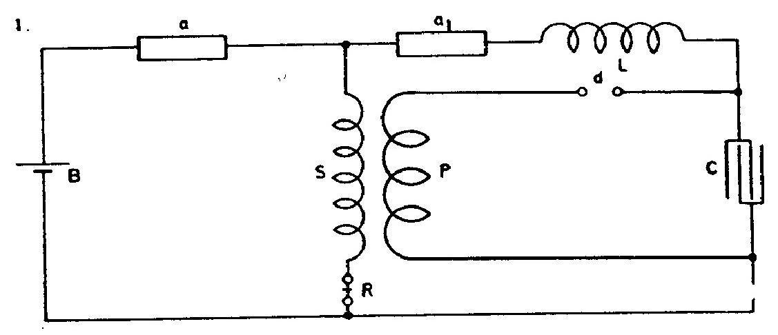
By changing connection to the one indicated in the second diagram the condenser was stronger and more effectively charged upon the falling of the resistance of either of the devices a a1.
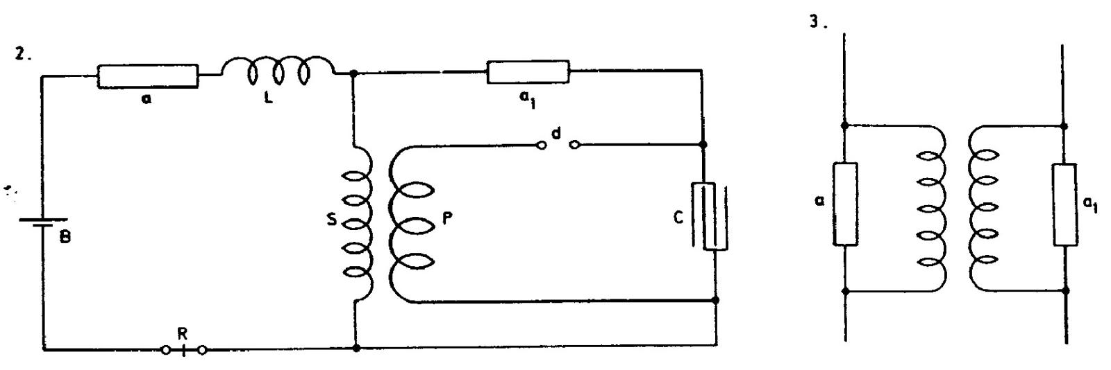
The conclusion arrived at from many experiments with two devices, which seem to indicate that two such sensitive devices are better than a single one as regards sensitiveness, was that the devices should be arranged as in Sketch 3 so that a change in one will produce a change in the other which in return should react upon the first and so on. This general scheme is to be further considered.
150
August 13
The last experiments with the oscillator were described July 31st, with numerous comments and the remark “this to follow up”. Probably he had prepared a new condenser bank in the meantime for work with higher voltages (he measured the capacitance of the new bottles on August 11th, and tried them out with the highest voltage so far from the power supply transformer.
August 13-14
Based on the earlier discoveries in this period, Tesla tests various apparatus modifications with "capacitor methods for the purpose of effects amplification". All mentioned receiver schematics, of which there are over 50, contain at least one battery, sensitive device, capacitor, rotating breaker, and high frequency transformer. In some schematics the relay for received signals is drawn, and in some that is understood, and it is not drawn. Also, except in one case (Aug. 5, Fig. 1), the plates by means of which the excitation of the sensitive device is obtained were not drawn up. For these plates, Tesla says that they could be in one or in two locations. This means that both plates could be in the air or both in the ground, or one in the ground, and the other in the air, if possible at the proper height. In patent(8), besides the mentioned locations for positioning of the plates, the following is cited: "They could be either linked with a distributed conductor, or they could be connected to the terminals of any apparatus which produces the electrical energy, which is obtained from the impulse energy or disturbances transmitted from a distance through natural media".
Considering the operating mode of various receivers, they have in common that the sensitive device pre-excitation is done by means of one battery. Receivers and Tesla's oscillators contain (rotating breaker which is driven by clock mechanism) which creates additional pre-excitation of the sensitive device (or number of them). This pre-excitation by means of alternating impulses acts as a positive return link and quickly switches the sensitive device on immediately after an initial disturbance caused by the signal. In the receiver with these two sensitive devices, one device is excited from the outside and normally from the primary side and the other device, which powers the receiver's relay, from the secondary side. In the receiver with one sensitive device normally the transformer secondary (of large impedance in order to prevent the disturbance of device operation) is connected in parallel with the sensitive device and so the efficient return link is obtained.
In two cases (Fig. 4 and 5, August 3), instead of a sensitive device with metal powder, the use of a dielectric which is exposed to an electrical field of such intensity that it is very close to flash-over state is assumed.
A number of schemes contain two sensitive devices and two batteries (Aug. 5). On Aug. 6, Tesla describes three schemes of the apparatus in various phases of improvements. These receivers were operating with only one dry-cell of a Leclanche battery!
On Aug. 7, he switches to the description of groups of receivers in which the sensitive device is positioned in the secondary circuit. From the previous experiments, Tesla concluded that some schemes with the similar elements layout gave good results. The reason for that could be found in the position of the sensitive device which is before the excitation in the circuit of high impedance. So even a weak signal from the high impedancy source (circuit area - ground) excited easily. Tesla observed that the increased sensitivity of the sensitive device is obtained by the indirect excitation from the secondary. Such a circuit was shown on Fig. 5. The excitation is performed by the induction (probably by means of an electric field). Because he stopped with this scheme, it is possible that there are some bad characteristics because of which he didn't continue the tests.
The general characteristic of the Tesla receivers is that they are delicate. The very careful adjusting is necessary in order to activate the sensitive device close to the flash-over point. Most of the sensitive devices Tesla rotated (please see June 23) so that they were in a state of good conductivity only for the duration of the signal. In some cases, however, the deactivating of the sensitive device was not obtained. Then he applied the electromagnetic buzzer by which he periodically interrupted the excitation of the sensitive device (please see Fig. 2, Aug. 8). Probably the scheme in Fig. 2 gave him the idea for the scheme in Fig. 3, where the rotating breaker is replaced by the electro-magnetic breaker. The electromagnetic breaker of the buzzer is positioned in some other comtinations (Fig. 5 and 6, Aug. 8). The goal of this layout is capacitor excitation, as well as that of the sensitive device, to the point of this device's flashover for reliable operation of the whole system.
Tesla didn't measure the sensitivity of his receivers by some defined method. Undoubtedly, however, he did compare them somehow with each other. From the notes described so far very little could be concluded about the sensitivity, or the exact amount of power which will activate the receivers. Some orientation of the obscure data were noted on July 4, when he used the similar receivers for the electrical discharge registration. By Tesla's estimate, the receiver registered waves created by lightning when the storm was at least 200 miles away and he could measure signals (in periodic time intervals) even later when the weather cleared up.
With the receiver given in the Fig. of July 28, he noted that in one case, it could register the electrical lightning discharge at a distance of 500 miles. The distance he estimated on the basis of periodical action of discharges when the storm was disappearing.
In Fig. 6 (Aug. 8) and Fig. 2, 3, 4 (Aug. 9), the schemes with two primary coils on the high frequency transformer are shown.
One produces the periodical pre-excitation and the second (probably) produces the impulse excitation. It is possible that Tesla desires to achieve deactivation automatically.
In the receiver operation, there was a possibility that contact D (rotating breaker) bypasses the Capacitor C. On Fig. 2, 3, 4 (Aug. 10) Tesla shows several schemes with two capacitors where this complication was avoided. Several schematic variations for achieving the-initial excitation, he considered on Aug. 11 (Figs. 1, 2, 3). On Fig. 41 the same day, he returns again to already known schemes (schemes shown on Fig. 1, Aug. 3, and Fig. 1, Aug. 6, differ from each other only in that they have L for the battery current regulation), and he makes a note that on this it is necessary to work further.
On Aug. 12, he again tests the possibility of the initial excitation of the sensitive device via high inductance (Fig. 1, 2, 3, and 4). On Fig. 5 and 6, he returns again to the transformer with two primaries, and on Fig. 7, 8, and 9, he shows several combinations with two batteries of which one serves for the purpose of initial excitation.
On Aug. 14, he experiments with circuits which contain two sensitive devices (Fig. 1, 2, 3) and adjusts the receiver's reaction time. He concludes that it is probably possible to achieve higher sensitivity with two sensitive devices, because it is possible that they influence each other successively. He plans further work with such dispositions. Other schemes given on Aug. 14 have only one sensitive device. In them several possibilities of connection between secondary and sensitive device as well as pre-excitation achievement are shown. On Fig. 6 and 7, it could be seen how aerial and ground are connected. The circuit on Fig. 6, contains inductance L1 which with C1 (aerial capacitance) form a resonant circuit which is adjusted to the oscillator frequency. On Fig. 7, secondary S is adjusted to the oscillator frequency*.
* The use of resonance in signal receiving Tesla suggested already in 1893 in his lectures at the Franklin Institute(6). Synchronized receiver he protected by a patent in 1897(14). Receiver, (actually entire receiver-transmitter system as well as in previous patent) with two resonant circuits for the purpose of receiving coded signals he described on June 27 in these notes, and protected them by patents(18) in 1900.
August 13
The last experiments with the oscillator were described on July 31 with numerous comments and remarks "to be continued". Probably in the meantime, the new capacitor battery was being prepared for the operation with higher voltages. On August 11, he performed the measurements of new capacitance jars, and on August 13 he tested them in operation with so far the highest voltage from the excitation network transformer. After the usual checking and various adjustments to the capacitance in the primary and secondary circuit of the oscillator, he registered sparks of almost three inches in length. Even better results were achieved with one turn in the primary and by adding "the additional coil" in the secondary. Comments about "lots of capacitance and a bit of inductance" in secondary are illustrative of Tesla's judgment of resonance conditions in the oscillator circuits.