Nikola Tesla Patents
Nikola Tesla U.S. Patent 1,314,718 - Ship's Log
NIKOLA TESLA, OF NEW YORK, N. Y., ASSIGNOR TO WALTHAM WATCH COMPANY, OF WALTHAM, MASSACHUSETTS, A CORPORATION OF MASSACHUSETTS.
TESLA PATENT 1,314,718 SHIP'S LOG.
| 1,314,718. | Specification of Letters Patent. | Patented Sept. 2, 1919. |
Application filed December 18, 1916. Serial No. 137,690.
To all whom it may concern:
Be it known that I, NIKOLA TESLA, a citizen of the United States, residing at New York, in the county and State of New York, have invented certain new and useful Improvements in Ship's Logs, of which the following is a full, clear, and exact description.
My invention provides a ship's log of novel and advantageous construction and operation, designed to give instantaneous rate-readings, as in knots, or miles per hour. The customary log is trailed astern, twisting the flexible connector that drives a revolution-counter on the vessel, and many disadvantages of such arrangement are obvious.
In my instrument I combine very advantageously a propeller rotatable proportionately to vessel-speed and a speed indicator driven by it and reading directly in the desired terms, preferably upon a substantially uniformly-graduated scale.
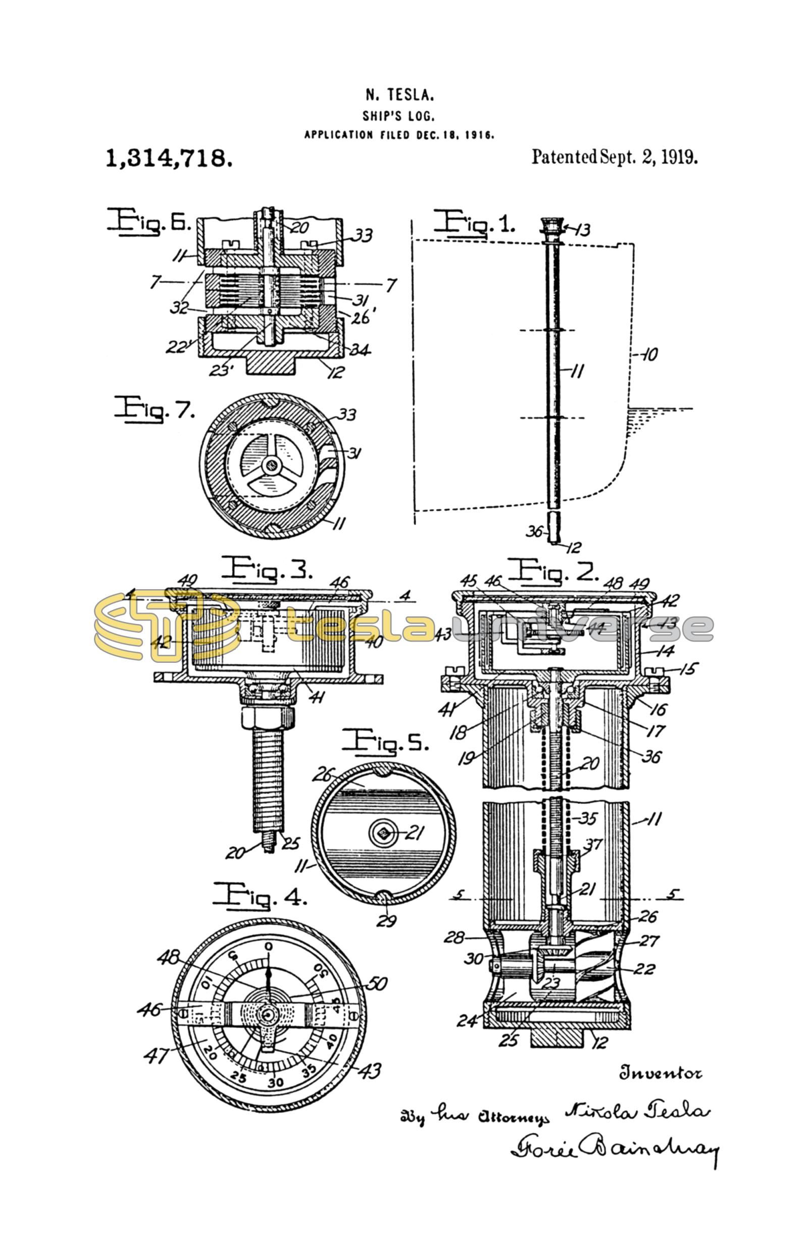
In the drawings, Figure 1 diagrams the log in use;
Fig. 2 shows it in vertical section;
Fig. 3 illustrates speed-indicator parts with the casing broken away;
Fig. 4 is a section on line 4—4 of Fig. 3;
Fig. 5 is a section on line 5—5 of Fig. 2.
Fig. 6 shows in section a turbine form of propeller, and
Fig. 7 is a section on line 7—7 of Fig. 6.
To the vessel 10, preferably near its bow, is suitably affixed a tube or barrel, 11, with a threaded plug 12 closing its lower end, where the tube preferably dips below the level of the boat's keel. At the top—near the deck or other point of observation—the speed-indicator 13 is mounted, its casing 14, that carries all of the moving parts being detachably secured, as by screws 15, to the top-flange 16 of the barrel. A boss 17 on the underside of casing 14 supports the ball bearing 18 for the primary element of the indicator and a seal 19 for its flexible driveshaft 20 that connects preferably through a slip-joint squared union, 21, to a propeller-driven part. The propeller may be of common form as shown in Fig. 2, at 22, with its shaft 23 horizontally mounted in the bracket 24 spanning the tubular passage 25 of a housing 26 that fits neatly in the barrel and is held in register with ports 27 and 28 by guide-ribs 29. Such a propeller drives the shaft 20 through bevel gears 30.
More advantageously in some respects, however, a turbine propeller of simple construction may be employed, as shown in Figs. 6 and 7. The rotor in this instance has a vertical shaft 23' and the wheel 22' is formed of thin, parallel, closely-spaced disks each having a central opening. The wheel is arranged in a cylindrical housing 26' that has inlet nozzles 31 and outlet ports 32 so disposed that the water enters the interspaces between the disks tangentially to rotate the wheel and finds escape through the ports 32 that communicate with the central orifices of the disks. This type of construction has many advantages due to its reliability and efficiency, but preferable it should be constructed to permit the disks and casing to be readily cleaned, casing 26' being made in two horizontal sections bolted together as at 33, each section having a detachable head 34.
A flexible and longitudinally elastic sleeve, 35, of coiled strip metal is fastened at opposite ends by threaded caps 36 and 37 to the boss 17 and to a threaded part on the propeller casing, so that the propeller mechanism is supported from the indicator casing for removal therewith.
By suitably constructing the submerged parts of bronze, enameling them, or otherwise making them substantially immune to corrosion, adequate durability is attained, and the facility of removal for cleaning, oiling, repairs, etc., makes the under-water parts easy to maintain in good order. The pliant shaft, slip-connected at one end and its stout protective sleeve, strong yet flexible and extensible frees the bearings from strain and makes the connection uniformly efficient under changes of conditions as to temperature, etc.
The speed indicator 13 preferably provides as its primary element 41 a multiple-walled cup, fast on shaft 20, and as a secondary, or indication-giving, member a lightly-constructed pivoted, multiple-walled inverted cup structure 42, with the annular walls interleaved in closely adjacent non-contacting relation for transmission of turning effort from the one to the other through intervening films of the casing-contained fluid medium, as air, in approximately linear proportion to the speed of the primary. Specifically the secondary cups are dependent from an arm 43 projecting from spindle 44, having jewel bearings in yoke 45 carried by bridge-piece, 46, that spans the casing 14, and the dial 47, calibrated according to a suitable constant to read in knots, or miles per hour or other units of rate, is borne by the cup-structure below a fixed hand 48 visible through the sealed cover-glass 49. A coiled spring 50, connected at its ends respectively to the pivoted secondary element and to a fixed support, resists the pivotal displacement of the indication-giving member. The light secondary element, quickly and accurately responsive approximately directly proportionately to the speed of the propeller-driven primary member, and little affected by tremors, temperature changes and other extraneous influences, gives adequately accurate readings in the desired terms, showing instantaneously changes of the vessel's speed.
What I claim is:
1. In ship's log, a barrel having water flow openings near its bottom, a speed-indicator detachably secured to one end of the barrel, a flexible shaft for the speed-indicator, a propeller connected to the shaft-end, a housing for the propeller, registering with the water-flow openings, and a sleeve surrounding the shaft uniting the housing and casing, for extraction of the propeller-parts when the speed-indicator is removed from the barrel.
2. In a ship's log, a barrel, a speed indicator having a casing secured detachably to the upper or observation end of the barrel, a propeller having a housing and adapted to pass through the barrel, a flexible shaft slip-fitted to connect the propeller and speed indicator, and a flexible sleeve connecting the propeller-housing and indicator-casing.
3. In a ship's log, the combination of a barrel having waterflow openings near its bottom, a speed indicator having a casing detachably secured to one end of the barrel, a shaft for said speed indicator extending centrally through the barrel, a propeller for the shaft end, a housing for the propeller, said housing being smaller than the barrel, and a sleeve surrounding the shaft uniting said housing and said indicator casing for effecting extraction of the propeller parts when the speed indicator is removed from the barrel.
4. In a ship's log, a barrel, a speed indicator having a casing secured detachably to the upper end of the barrel, a propeller having a housing and adapted to pass through the barrel, there being registering openings near the bottom of the barrel and in said housing for water-flow to the propeller, a flexible shaft connecting said propeller and speed indicator and making axially slidable connection with one thereof, and a flexible and axially expansible sleeve connecting the propeller housing and the indicator casing for extraction of the propeller parts when the speed indicator is removed from the barrel.
In testimony whereof I affix my signature.
NIKOLA TESLA.