Nikola Tesla Patents
Nikola Tesla U.S. Patent 433,702 - Electrical Transformer or Induction Device
NIKOLA TESLA, OF NEW YORK, N. Y., ASSIGNOR TO THE TESLA ELECTRIC COMPANY, OF SAME PLACE.
ELECTRICAL TRANSFORMER OR INDUCTION DEVICE.
SPECIFICATION forming part of Letters Patent No. 433,702, dated August 5, 1890.
Application filed May 26, 1890. Serial No. 345,390. (No model.)
To all whom it may concern:
Be it known that I, NIKOLA TESLA, a subject of the Emperor of Austria-Hungary, from Smiljan, Lika, border country of Austria-Hungary, residing at New York, in the county and State of New York, have invented certain new and useful Improvements in Electrical Transformers or Induction Devices, of which the following is a specification, reference being had to the drawings accompanying and forming a part of the same.
This invention is an improvement in electrical transformers or converters, and has for its main objects the provision of means for securing, first, a phase difference between the primary and secondary currents adapted to the operation of my alternating-current motors and other like purposes, and, second, a constant current for all loads imposed upon the secondary.
In transformers as constructed now and heretofore it will be found that the electro-motive force of the secondary very nearly coincides with that of the primary, being, however, of opposite sign. At the same time the currents, both primary and secondary, lag behind their respective electro-motive forces; but as this lag is practically or nearly the same in the case of each it follows that the maximum and minimum of the primary and secondary currents will nearly coincide, but differ in sign or direction, provided the secondary be not loaded or if it contain devices having the property of self-induction. On the other hand, the lag of the primary behind the impressed electro-motive force may be diminished by loading the secondary with a non-inductive or dead resistance—such as incandescent lamps—whereby the time interval between the maximum or the minimum periods of the primary and secondary currents is increased. This time interval, however, is limited, and the results obtained by phase difference in the operation of such devices as my alternating-current motors can only be approximately realized by such means of producing or securing this difference, as above indicated, for it is desirable in such cases that there should exist between the primary and secondary currents, or those which, however produced, pass through the two circuits of the motor, a difference of phase of ninety degrees; or, in other words, the current in one circuit should be maximum when that in the other circuit is minimum. To more perfectly attain to this condition I obtain or secure an increased retardation of the secondary current in the following manner: Instead of bringing the primary and secondary coils or circuits of a transformer into the closest possible relations, as has hitherto been done, I protect in a measure the secondary from the inductive action or effect of the primary by surrounding either the primary or the secondary with a comparatively-thin magnetic shield or screen. Under these conditions or circumstances, as long as the primary current has a small value, the shield protects the secondary; but as soon as the primary current has reached a certain strength, which is arbitrarily determined, the protecting magnetic shield becomes saturated and the inductive action upon the secondary begins. It results, therefore, that the secondary current begins to flow at a certain fraction of a period later than it would without the interposed shield, and since this retardation may be obtained without necessarily retarding the primary current also, an additional lag is secured, and the time interval between the maximum or minimum periods of the primary and secondary currents is increased. I have further discovered that such a transformer may, by properly proportioning its several elements and determining in a manner well understood the proper relations between the primary and secondary windings, the thickness of the magnetic shield, and other conditions, be constructed to yield a constant current at all loads. No precise rules can be given for the specific construction and proportions for securing the best results, as this is a matter determined by experiment and calculation in particular cases; but the general plan of construction which I have described will be found under all conditions to conduce to the attainment of this result.
In the accompanying drawings I have illustrated the construction above set forth.
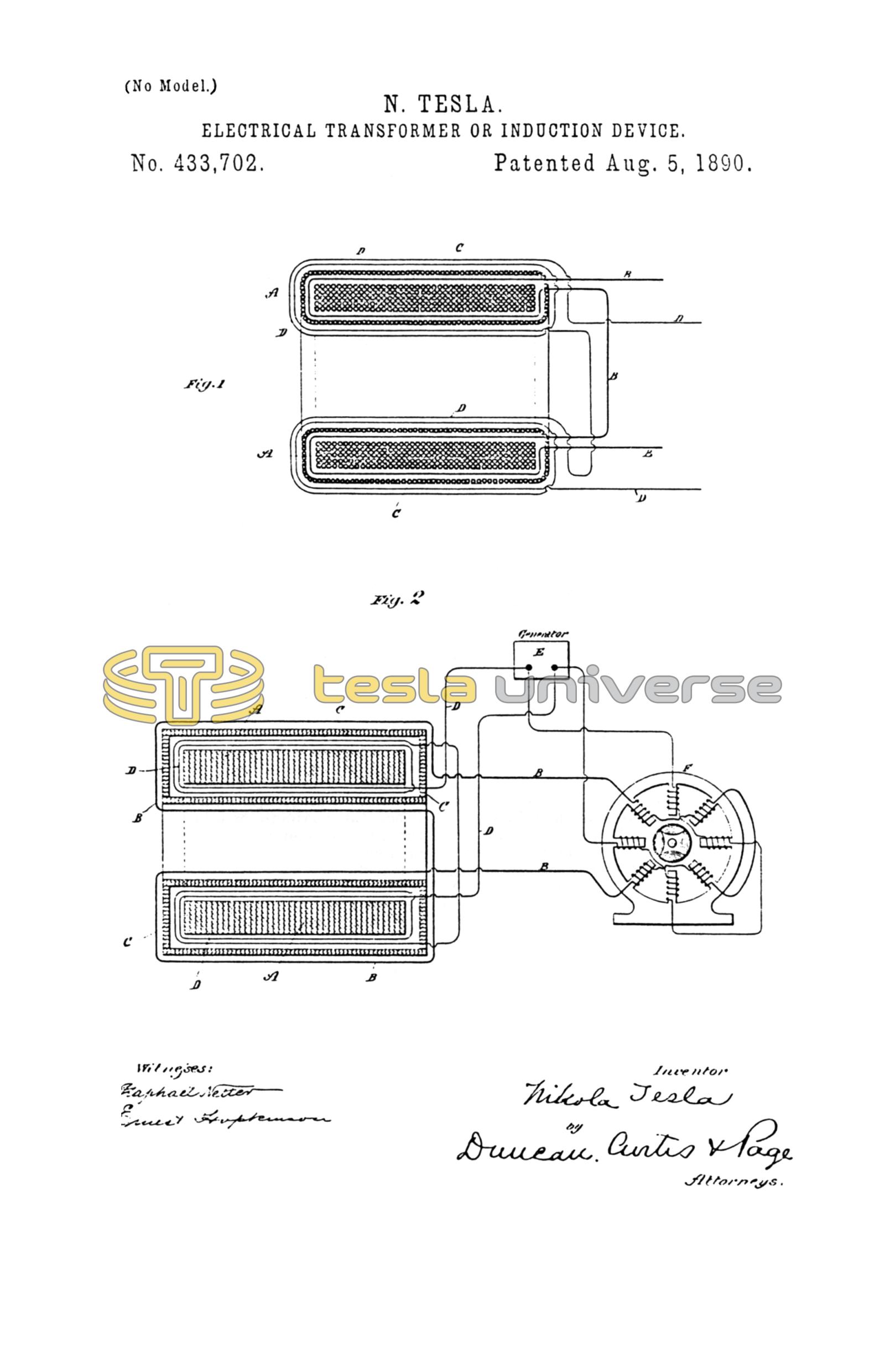
Figure 1 is a cross-section of a transformer embodying my improvement. Fig. 2 is a similar view of a modified form of transformer, showing diagrammatically the manner of using the same.
A A is the main core of the transformer, composed of a ring of soft annealed and insulated or oxidized iron wire. Upon this core is wound the secondary circuit or coil B B. This latter is then covered with a layer or layers of annealed and insulated iron wires C C, wound in a direction at right angles to said secondary coil. Over the whole is then wound the primary coil or wire D D. From the nature of this construction it will soon be obvious that as long as the shield formed by the wires C is below magnetic saturation the secondary coil or circuit is effectually protected or shielded from the inductive influence of the primary, although I would state that on open circuit it may exhibit some electro-motive force. When the strength of the primary reaches a certain value, the shield C, becoming saturated, ceases to protect the secondary from inductive action, and current is in consequence developed therein. For similar reasons, when the primary current weakens, the weakening of the secondary is retarded to the same or approximately the same extent.
The specific construction of the transformer is largely immaterial. In Fig. 2, for example, the core A is built up of thin insulated iron plates or disks. The primary circuit D is wound next the core A. Over this is applied the shield C, which in this case is made up of thin strips or plates of iron properly insulated and surrounding the primary, forming a closed magnetic circuit. The secondary B is wound over the shield C. In Fig. 2, also, E is a source of alternating or rapidly changing currents. The primary of the transformer is connected with the circuit of the generator.
F is a two-circuit alternating-current motor, one of the circuits being connected with the main circuit from the source E, and the other being supplied with currents from the secondary of the transformer.
Having now described my invention, what I claim is—
1. In an electrical transformer or induction device, the combination, with the main magnetic core and the primary and secondary coils or circuits, of a magnetic shield or screen interposed between said coils, as herein set forth.
2. In an electrical transformer or inductive device, the combination, with the magnetic core and the primary and secondary coils or circuits, of a magnetic shield or screen surrounding one of said coils only, as set forth.
3. In an electrical transformer or induction device, the combination, with the magnetic core and the primary and secondary coils wound thereon, of a magnetic shield or screen wound on or built up around one only of said coils, as described.
4. In an electrical transformer or induction device, the combination, with a main laminated magnetic core and primary and secondary coils thereon, of a subdivided or laminated magnetic shield or screen interposed between the coils, as set forth.
5. In an electrical transformer, the combination, with a magnetic core and primary and secondary coil wound thereon, of a magnetic shield or screen interposed between said coils and surrounding one of them and adapted to be or capable of being magnetically saturated by a predetermined current strength below the maximum in the primary, as set forth.
NIKOLA TESLA.
ROBT. F. GAYLORD,
PARKER W. PAGE.