Nikola Tesla Patents
Nikola Tesla U.S. Patent 455,069 - Electric Incandescent Lamp
NIKOLA TESLA, OF NEW YORK, N. Y.
ELECTRIC INCANDESCENT LAMP.
SPECIFICATION forming part of Letters Patent No. 455,069, dated June 30, 1891.
Application filed May 14, 1891. Serial No. 392,669. (No model.)
To all whom it may concern:
Be it known that I, NIKOLA TESLA, a subject of the Emperor of Austria, from Smiljan, Lika, border country of Austria-Hungary, residing at New York, in the county and State of New York, have invented certain new and useful Improvements in Electric Incandescent Lamps, of which the following is a specification, reference being had to the accompanying drawings.
My invention is a new form of lamp for giving light by the incandescence of carbon or other suitable refractory conductor produced by electrical energy.
In order to more distinctly point out those features which distinguish my invention, I would state that heretofore electric lamps have been made, first, by mounting a refractory conductor on metallic supporting-wires leading into a hermetically-sealed receiver from which the air has been exhausted or replaced by an inert gas, and, second, by placing two independent conductors in a receiver or globe and partially exhausting the air therefrom. In the first case the carbon or other conductor is rendered incandescent by the actual flow or passage of a current through it, while in the second the luminous effects, as heretofore produced, or, in fact, the only luminous effects that could be produced by any means heretofore known, were due to an actual discharge of current from one conductor to the other across the intermediate space of rarefied air or gas.
It may be further remarked that in various forms of Geissler or vacuum tubes the terminals or points within the tube become or have a tendency to become heated by the action of the high-tension secondary discharge. In such tubes, however, the degree of exhaustion is comparatively low, as a high vacuum prevents the well-known Geissler discharge or effect. Moreover, with such low degrees of exhaustion the points or wires, if heated and allowed to become incandescent, are speedily destroyed.
I have discovered that two conducting-bodies mounted in a very highly exhausted receiver may be rendered incandescent and practically utilized as a source of light if connected directly or inductively to the terminals of a source of current of very great frequency and very high potential.
The practical requirements of this invention are widely different from those employed in producing any of the phenomena heretofore observed, such differences being mainly in respect to the current, which must be one of enormous frequency and of excessively high potential, and also to the degree of exhaustion of the globe or receiver, which must be carried at least beyond the point at which a spark will pass, or to the condition known as a “non-striking vacuum,” and it may be as much farther as possible.
This application is confined to a particular form of lamp which I employ in a new system invented by me, which system involves, as one of its essential characteristics, the employment of currents or electric effects of a novel kind. In an application filed by me April 25, 1891, No. 390,414, I have shown and described this system in detail, and I therefore deem it sufficient for the present case to say that the lamps herein described, while utterly inoperative on any of the circuits now, or, so far as I am aware, heretofore employed become highly efficient sources of light if the frequency of the current by which they are operated be sufficiently great and the potential sufficiently high. To produce such currents, any known means may be utilized or the plan described in my said application followed of disruptively discharging the accumulated energy in a condenser into or through a primary circuit to produce a current of very high frequency, and inducing from this current a secondary current of a very much higher potential.
I now refer to the drawings in illustration of the invention.
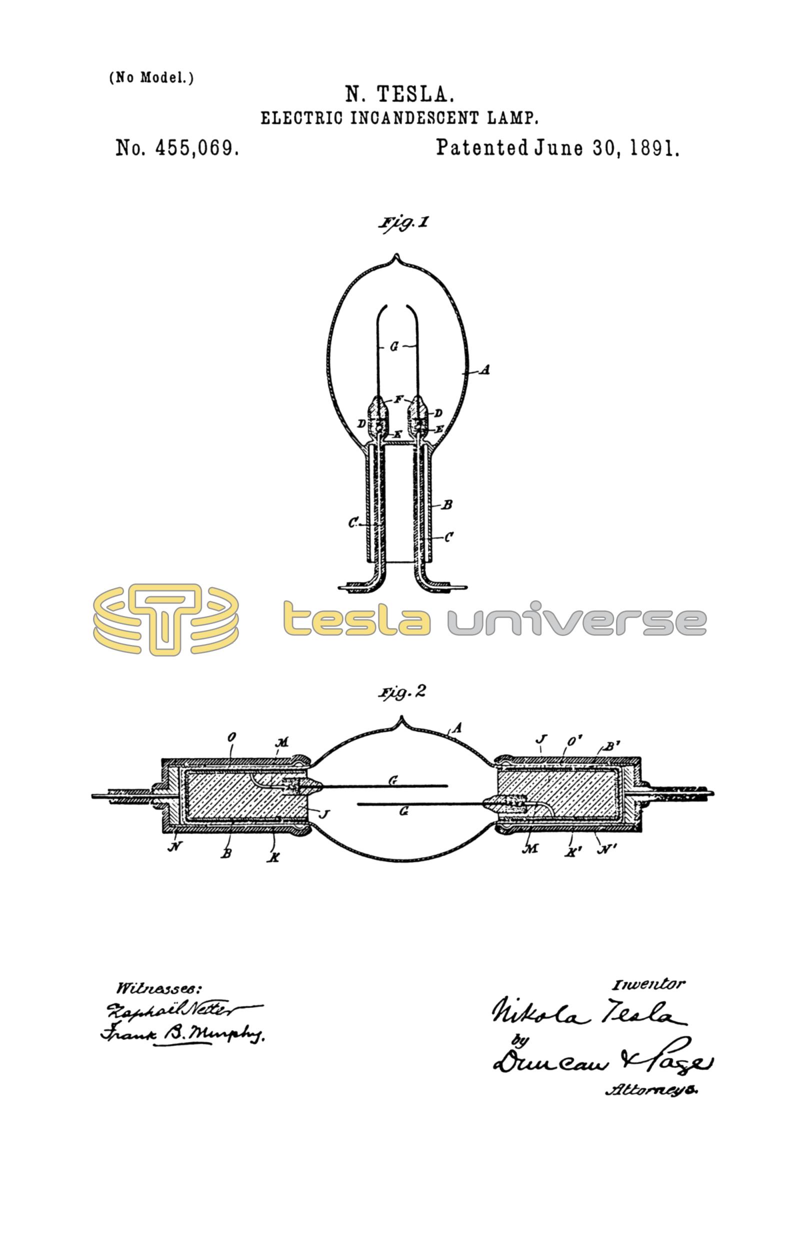
Figure 1 is a vertical sectional view of a lamp constructed with leading-in wires for direct connection with a circuit or source of current. Fig. 2 is a similar view of a form of lamp arranged for inductive connection with such source.
The common methods or steps followed in the manufacture of the ordinary incandescent lamps and Geissler tubes may be employed in the manufacture of these improved lamps as far as applicable.
A is a glass globe or receiver with a neck or base B. Conducting-wires C C enter this globe and are sealed in the walls thereof. The entering wires C are surrounded by small tubes or cups D. The joints between the wires C and the incandescing conductors are made within these cups in any ordinary manner, and the lower parts of the cups are filled with bronze-powder E or other suitable material to effect a good electrical connection. The cups are then filled up with fire-clay or other refractory non-conductor F, which is molded around the carbons G. The carbons or other refractory conductors or semi-conductors G are completely isolated from one another. They are here shown as slender strips; but they may have any other desired shape. Lamps thus made are attached to a vacuum-pump in the usual way. After the process of exhaustion has been carried on for some time they are brought to incandescence by a suitable current, by which the fire-clay is thoroughly baked and the occluded gases are driven off. The exhaustion is carried to the highest possible point, and the globe finally sealed off at H. Inasmuch as there is a tendency to sparking when the current is turned on before the exhaustion has been carried very high, it is well, when the character of the carbon admits of it, to cause their ends to approach, in order that the sparks may leap across between such points, whereby the danger of injury to the carbons or the lamp is lessened. The conductors outside the globe, as well as all those which convey the current from the source, should be carefully insulated to prevent the dissipation of the current.
In lieu of connecting the two carbons directly to the circuit through leading-in wires, provision may be made for inductively connecting them, as by means of condensers. Fig. 2 shows a form of lamp of this description that I have employed. The globe A has two extended tubular portions B B'. Inside of these tubular extensions are condenser-coatings K K'.
J J are plugs of fire-clay or the like contained in the extensions B B'. The two conductors G G are supported by these plugs and connected by metallic strips M with the condenser-coatings K K', respectively. Over the outside of the extensions B B' are fitted insulating-caps N N', having metallic linings O O', with terminals adapted for connection with the circuit-wires. With such currents as are employed to operate these lamps condensers of small capacity, such as those thus made, transmit the energy from the outside circuit to the carbons within the globe with little loss. This lamp is exhausted and sealed off from the pump in the same manner as that first described. There is no electrical connection at any time between the two carbons of this lamp and no visible discharge or transfer of current from one to the other through the highly-rarefied medium between them. The fact, therefore, of their being rendered incandescent by the action of such a current as I have described seems to be mainly attributable to condenser action.
The carbons, or whatever substance may be used in their stead, may be of any desired form and may be placed in different relative positions.
The manner of making the lamp and the general form of the lamp as a whole may be varied in numberless ways. I have merely shown herein typical forms which embody the principle of the invention and which by experience I have demonstrated to be practical lamps.
As the lamps which I employ and which are made as above described are absolutely inoperative in any system from which the hereinbefore-described conditions of potential and frequency are absent, so the various lamps heretofore devised for use with high-potential currents, in which the exhaustion, of necessity, has not been carried to or beyond the non-striking point, are practically worthless in my new system, and this is the distinguishing feature of novelty in my lamps—viz., that they are exhausted to or beyond the non-striking point.
What I claim as my invention is—
1. An incandescent lamp consisting of two isolated refractory conductors contained in a non-striking vacuum and adapted to produce light by incandescence, each being provided with a terminal for connection with a source of electrical energy, as set forth.
2. The combination, with a globe or receiver exhausted to the non-striking point, of two isolated bodies of refractory conducting material adapted to emit light by incandescence and mounted within said globe, and means for connecting said bodies with the two poles or terminals, respectively, of a source of electrical energy.
3. In an incandescent electric lamp, the combination, with a globe or receiver exhausted to the non-striking point, of metallic wires sealed therein, a refractory body mounted on or electrically connected to each wire, the said wires within the globe and such parts of the refractory body as are not to be rendered incandescent being coated or covered with insulation, as set forth.
4. The combination, with a globe or receiver exhausted to the non-striking point, of metallic wires sealed therein, a refractory conductor united to each of said wires within the globe, an insulating-covering around the wires and joint, and a refractory insulating-body surrounding the refractory conductors near the joint, as set forth.
NIKOLA TESLA.
ROBT. F. GAYLORD,
PARKER W. PAGE.