Nikola Tesla Patents
Nikola Tesla U.S. Patent 514,972 - Electric Railway System
NIKOLA TESLA, OF NEW YORK, N. Y.
ELECTRIC-RAILWAY SYSTEM.
SPECIFICATION forming part of Letters Patent No. 514,972, dated February 20, 1894.
Application filed January 2, 1892. Serial No. 416,774. (No model.)
To all whom it may concern:
Be it known that I, NIKOLA TESLA, a citizen of the United States, residing at New York, in the county and State of New York, have invented certain new and useful Improvements in Electric-Railway Systems, of which the following is a specification, reference being had to the drawings accompanying and forming a part of the same.
This invention is an improved system or plan of supplying electric current to the motors of street or other cars or vehicles from a central or stationary source of supply, without the use of sliding or rolling contacts between the line conductor and the car motors. I use in my system alternating or pulsating currents of very high potential, and, by reason mainly of the higher economy, high frequency. The conductor which conveys these currents is run from the stationary source of supply along the line of travel and preferably through a conduit constructed between, or alongside of the tracks or rails.
To prevent the dissipation of the electric energy that would otherwise occur on a circuit conveying currents of the character which I use, I insulate the line conductor and surround it with a conducting coating that serves as a screen, and I prefer, mainly with the object of localizing the action that would result from the establishment of an electrical connection between the screen and the ground or other conducting body, to divide up the outer conductor into insulated sections of comparatively short length. In the car, or to each of a number running on a given track, equipped in accordance with my invention, I attach an arm carrying a conducting plate or bar that is electrically connected with the motor coils and which by the movement of the car is carried in proximity to the line conductor, so as to take off, by condenser action, sufficient energy to run the car motor.
The details of the invention, and the best manner I am aware of in which it is or may be carried out, I shall explain by reference to the accompanying drawings.
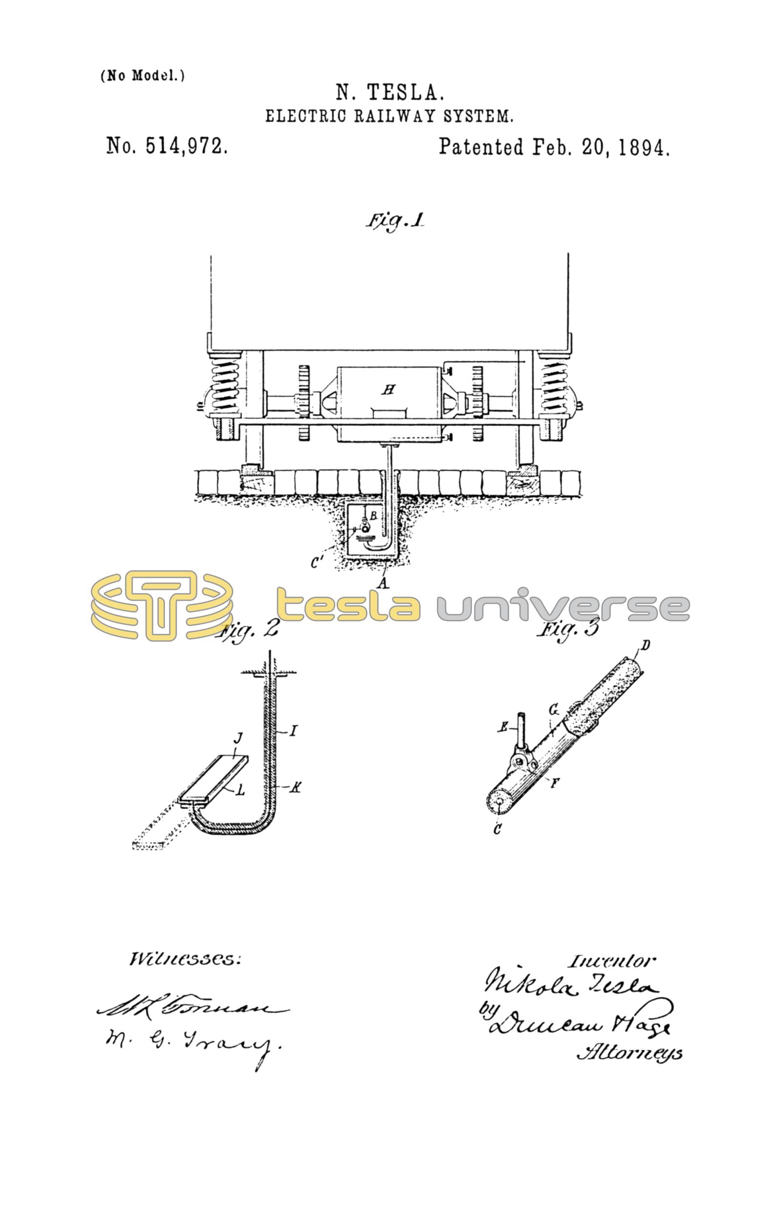
Figure 1 is a view showing a portion of a car and the means for supplying the motor of the same with current from a line conductor supported within a conduit between the rails. Fig. 2 is an enlarged sectional view of the arm carrying the conductor through which the electric energy is transmitted from the line conductor to the motor. Fig. 3 is an enlarged view partly in section of the line conductor.
I propose to employ an iron conduit A, which is buried preferably between the rails of the track and provided with a longitudinal slot along its top close to one edge or side. A flange B is formed or applied along the slot, forming a protected chamber or compartment for containing the line conductor. This chamber should be of such form in cross-section that its walls will be symmetrically disposed with respect to the conductor running through it, and thus reduce to a minimum any disturbing inductive effects which would be produced by an unsymmetrical disposition of the walls with respect to the conducting screen or covering around the conductor.
For the line conductor I employ a suitable wire C, surrounded by an insulated coating D, which is enclosed in a metallic sheathing G. For the latter I prefer to use iron pipes provided with perforated lugs F, by means of which the conductor is suspended by insulated rods or other devices E. I also divide up the conducting screen or sheathing into sections insulated from one another, but overlapping so as to leave no breaks in the screen. The advantage in dividing up the screen in this manner is that the loss due to currents induced in the outer conductor is reduced, while at the same time the grounding of any one section would result in a very small loss compared with what would take place from a continuous sheath; moreover, by overlapping the ends of the sections but little opportunity is afforded for the dissipation of energy.
The car is represented as carrying a motor H, which may be of any suitable construction and capable of being operated by currents of the kind employed. Connected with the motor or car is an iron or conducting tube I, that extends down into the conduits through the slots therein. The lower end of this tube is bent in the form of a hook and supports within the conductor chamber a bar or plate J that presents to the line conductor a conducting surface. This bar or plate is electrically connected with the motor coils by an insulated wire K, that passes up through the tube I, and all parts of the said plate except the surface exposed to the conductor C, or its metallic sheath, are insulated and protected by a metallic screen L. It is obvious that all portions of the arm as well as the plate itself may be insulated as by a water-proof covering, and it will be understood that the principal object of the invention would still be attained even though the plate were in actual contact with the screen while the car is in motion.
In operation, the line conductor C is connected with a source of current of very high potential and great frequency. This current may be conveyed to any desired distance without material loss, as the insulated metallic covering or sheath around the conductor serves as a static screen to prevent the dissipation of the energy. The presence, however, of a plate J of any car close to the sheath or screen disturbs the electrical equilibrium and sets up by condenser action a transfer of energy from the screen to the plate sufficient to operate the motor on the car.
In the above, I have described the screen, whether continuous or subdivided, as wholly insulated from the ground or surrounding conducting bodies, but the single continuous screen or each section of the same, may be connected to the ground through a condenser of relatively very small capacity, through a device of high self-induction or resistance, as shown in dotted lines at C' in Fig. 1.
I do not claim in this application the particular line conductor described, nor the broad idea of inducing from a stationary conductor the current to operate the motor on a traveling car or other vehicle, but
What I claim is—
1. In an electric railroad system operated by electric currents of high potential and frequency, the combination of an insulated and electrically screened supply conductor extending along the line of travel, a motor car or cars carrying a conducting plate or bar in inductive relation to the screened conductor and an electrical connection between the said plate and the motor, as set forth.
2. In an electric railroad system operated by electric currents of high potential and frequency, the combination of a supply conductor running along the line of travel, a conducting sheath or screen divided into insulated sections and surrounding the said conductor, a motor car supporting a conducting body in proximity to the supply conductor and an electrical connection between said body and the motor as set forth.
3. In an electrical railway system, the combination with a slotted conduit of an insulated conductor supported therein, an insulated sheath or screen surrounding the conductor, a motor car adapted to run on tracks parallel with the conduit, a conducting plate or bar carried by an arm descending from the car into the conduit, and an electrical connection between the plate and the motor, as set forth.
NIKOLA TESLA.
ERNEST HOPKINSON,
PARKER W. PAGE.