Nikola Tesla Patents
Nikola Tesla U.S. Patent 517,900 - Steam Engine
NIKOLA TESLA, OF NEW YORK, N. Y.
STEAM-ENGINE.
SPECIFICATION forming part of Letters Patent No. 517,900, dated April 10, 1894.
Application filed December 29, 1893. Serial No. 495,079. (No model.)
To all whom it may concern:
Be it known that I, NIKOLA TESLA, a citizen of the United States, residing at New York, in the county and State of New York, have invented certain new and useful Improvements in Steam-Engines, of which the following is a specification, reference being had to the drawings accompanying and forming a part of the same.
Heretofore, engines, operated by the application of a force such as the elastic tension of steam or a gas under pressure, have been provided with a fly-wheel, or some rotary system equivalent in its effect and possessing relatively great mechanical inertia, which was relied upon for maintaining a uniform speed. I have produced however, an engine which without such appurtenances produces, under very wide variations of pressure, load, and other disturbing causes, an oscillating movement of constant period, and have shown and described the same in an application filed on August 19, 1893, Serial No. 483,563. A description of the principle of the construction and mode of operation of this device is necessary to an understanding of my present invention. When a spring which possesses a sensible inertia is brought under tension as by being stretched and then freed, it will perform vibrations which are isochronous and, as to period, mainly dependent upon the rigidity of the spring and its own inertia or that of the moving system of which it forms an immediate part. This is known to be true in all cases where the force which tends to bring the spring or movable system into a given position is proportionate to the displacement. In utilizing this principle for the purpose of producing reciprocating movement of a constant period, I employ the energy of steam or gas under pressure, acting through proper mechanism, to maintain in oscillation a piston, and connect with or cause to act upon such piston a spring, preferably, an air spring, under such conditions as to automatically regulate the period of the vibration, so that the alternate impulses of the power impelled piston and the natural vibrations of the spring shall always correspond in direction and coincide in time. In such an apparatus it being essential that the inertia of the moving system and the rigidity of the spring should bear certain definite relations, it is obvious that the practicable amount of work performed by the engine, when this involves the overcoming of inertia is a limitation to the applicability of the engine. I therefore propose, in order to secure all the advantages of such performances as this form of engine is capable of, to utilize it as the means of controlling the admission and exhaust of steam or gas under pressure in other engines generally, but more especially those forms of engine in which the piston is free to reciprocate, or in other words, is not connected with a fly wheel or other like device for regulating or controlling its speed.
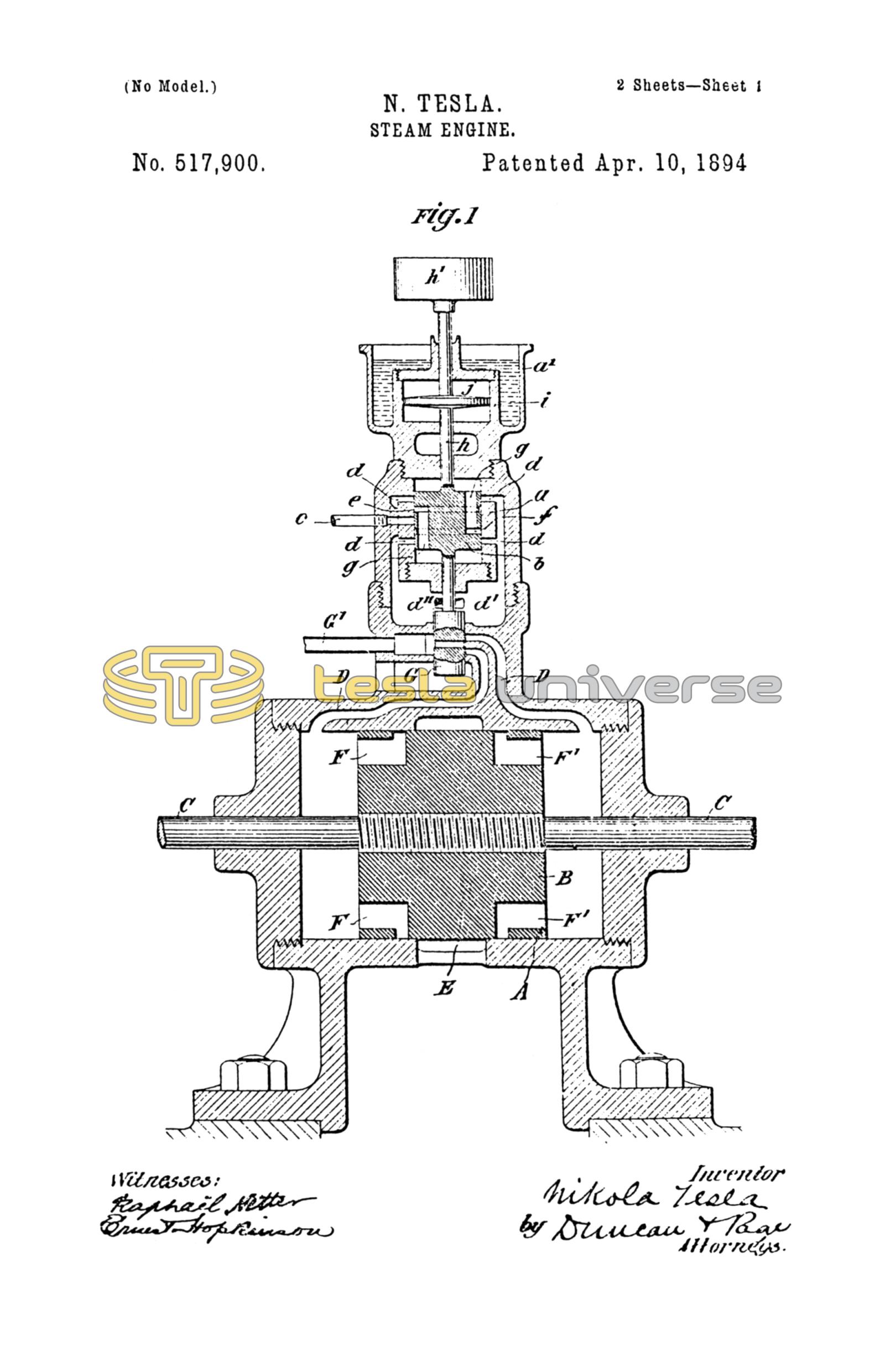
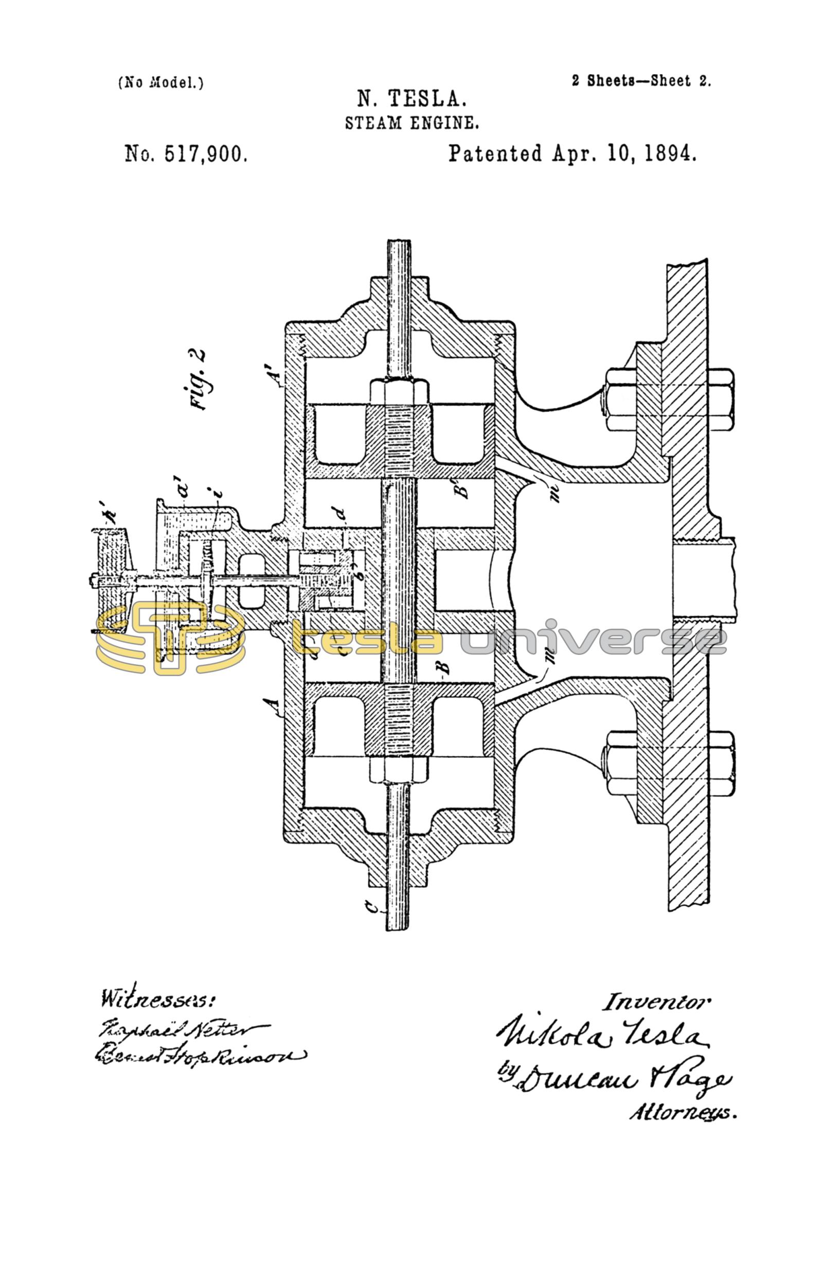
The drawings hereto annexed illustrate devices by means of which the invention may be carried out, Figure 1 being a central vertical section of an engine embodying my invention, and Fig. 2 a similar view of a modification of the same.
Referring to Fig. 1, A designates a cylinder containing a reciprocating piston B secured to a rod C extending through one or both cylinder heads.
D D' are steam ducts communicating with the cylinder at or near its ends and E is the exhaust chamber or passage located between the steam ports. The piston B is provided with the usual passages F F' which by the movements of the piston are brought alternately into communication with the exhaust port.
G designates a slide valve which when reciprocated admits the steam or the gas by which the engine is driven, from the pipe G' through the ducts D D' to the ends of the cylinder.
The parts thus described may be considered as exemplifying any cylinder, piston and slide valve with the proper ports controlled thereby, but the slide valve instead of being dependent for its movement upon the piston B is connected in any manner so as to be reciprocated by the piston rod of a small engine of constant period, constructed substantially as follows:—a is the cylinder, in which works the piston b. An inlet pipe c passes through the side of the cylinder at the middle portion of the same. The cylinder exhausts through ports d d into a chamber d' provided with an opening d''. The piston b is provided with two circumferential grooves e, f which communicate through openings g in the same with the cylinder chambers on opposite sides of the piston. The special construction of this device may be varied considerably, but it is desirable that all the ports, and more particularly, the exhaust ports be made larger than is usually done, so that no force due to the action of the steam or compressed air in the chambers will tend to retard or accelerate the movement of the piston in either direction. The piston b is secured to a rod h which extends through the cylinder heads, the lower end carrying the slide valve above described and the upper end having secured to it a plunger j in a cylinder i fixed to the cylinder a and in line with it. The cylinder i is without ports of any kind and is air-tight except that leakage may occur around the piston rod which does not require to be very close fitting, and constitutes an ordinary form of air spring.
If steam or a gas under pressure be admitted through the port c to either side of the piston b, the latter, as will be understood, may be maintained in reciprocation, and it is free to move, in the sense that its movement in either direction ceases only when the force tending to impel it and the momentum which it has acquired are counterbalanced by the increasing pressure of the steam in that end of the cylinder toward which it is moving, and as in its movement the piston has shut off at a given point, the pressure that impelled it and established the pressure that tends to return it, it is then impelled in the opposite direction, and this action is continued as long as the requisite pressure is applied. The movements of the piston compress and rarefy the air in the cylinder i at opposite ends of the same alternately, and this results in the heating of the cylinder. But since a variation of the temperature of the air in the chamber would affect the rigidity of the air spring, I maintain the temperature uniform as by surrounding the cylinder i with a jacket a' which is open to the air and filled with water.
In such an engine as that just above described the normal pressure will produce a stroke of determined length, which may be increased or diminished according to the increase of pressure above or the reduction of pressure below the normal and due allowance is made in constructing the engine for a variation in the length of stroke. The rate or period of reciprocation of the piston, however, is no more dependent upon the pressure applied to drive it, than would be the period of oscillation of a pendulum permanently maintained in vibration, upon the force which periodically impels it, the effect of variations in such force being merely to produce corresponding variations in the length of stroke or amplitude of vibration respectively. The period is mainly determined by the rigidity of the air spring and the inertia of the moving system and I may therefore secure any period of oscillation within very wide limits by properly proportioning these factors, as by varying the dimensions of the air chamber which may be equivalent to varying the rigidity of the spring, or by adjusting the weight of the moving parts. This latter is readily accomplished by making provision for the attachment to the piston rod of one or more weights h'. Since the only work which the small engine has to perform is the reciprocation of the valve attached to the piston rod, its load is substantially uniform and its period by reason of its construction will be constant. Whatever may be the load on the main engine therefore the steam is admitted to the cylinder at defined intervals, and thus any tendency to a change of the period of vibration in the main engine is overcome.
The control of the main engine by the engine of constant period may be effected in other way—of which Fig. 2 will serve as an illustration. In this case the piston of the controlling engine constitutes the slide valve of the main engine, so that the latter may be considered as operated by the exhaust of the former. In the figure I have shown two cylinders A A' placed end to end with a piston B and B' in each. The cylinder of the controlling engine is formed by or in the casing intermediate to the two main cylinders but in all other essential respects the construction and mode of operation of the controlling engine remains as described in connection with Fig. 1. The exhaust ports d d however, constitute the inlet ports of the cylinders A A' and the exhaust of the latter is effected through the ports m, m which are controlled by the pistons B and B' respectively. The inlet port for the admission of the steam to the controlling engine is similar to that in Fig. 1 and is indicated by the dotted circle at the center of the piston b.
An engine of the kind described possesses many and important advantages. A much more perfect regulation and uniformity of action is secured, while the engine is simple and its weight for a given capacity is very greatly reduced. The reciprocating movement of the piston may be converted, by the ordinary mechanisms into rotary motion or it may be utilized and applied in any other manner desired, either directly or indirectly.
In another application of even date herewith I have shown and described two reciprocating engines combined in such manner that the movement or operation of one is dependent upon and controlled by the other. In the present case, however, the controlling engine is not designed nor adapted to perform other work than the regulation of the period of the other, and it is moreover an engine of defined character which has the capability of an oscillating movement of constant period.
What I claim is—
1. The combination with the cylinder and reciprocating piston and controlling valve of an engine adapted to be operated by steam or a gas under pressure of an independently controlled engine of constant period operating the said valve, as described.
2. The combination of an engine cylinder, a piston adapted to reciprocate therein, a slide valve for controlling the admission of steam to said cylinder, and an independently controlled engine of constant period operatively connected with said valve.
3. The combination with the cylinder, piston and valve mechanism of a main or working engine, of an independent controlling engine comprising a cylinder, a piston connected with the valve mechanism of the main engine, and a spring acting upon the said piston and controlling the period of its reciprocation, as set forth.
4. The combination with a cylinder and a piston adapted to be reciprocated by steam or a gas under pressure of a cylinder and a plunger therein reciprocated by the piston and constituting with its cylinder an air spring, and an open jacket or receptacle around the said cylinder and containing water to preserve the temperature of the air spring uniform, as set forth.
5. The combination with a cylinder, a reciprocating piston and valve mechanism for controlling the admission and exhaust of the steam or gas under pressure, of a cylinder, a piston connected with and operating said valve mechanism, and an air spring vibrated by the piston, the spring and piston being related in substantially the manner described to produce a reciprocating movement of constant period.
NIKOLA TESLA.
ARTHUR H. SMITH,
ERNEST HOPKINSON.