Nikola Tesla Patents
Nikola Tesla U.S. Patent 611,719 - Electrical Circuit Controller
NIKOLA TESLA, OF NEW YORK, N. Y.
ELECTRICAL-CIRCUIT CONTROLLER.
SPECIFICATION forming part of Letters Patent No. 611,719, dated October 4, 1898.
Application filed December 10, 1897. Serial No. 661,403. (No model.)
To all whom it may concern:
Be it known that I, NIKOLA TESLA, residing at New York, in the county and State of New York, have invented certain new and useful Improvements in Electrical-Circuit Controllers, of which the following is a specification, reference being had to the drawings accompanying and forming a part of the same.
In order to secure a more efficient working of circuit-controllers, particularly in their use in connection with my system of electrical-energy conversion by means of condenser discharges, I have devised certain novel forms of such appliances, comprising as essential elements a body of conducting fluid constituting one of the terminals, a conductor or series of conductors forming the other terminal, and means for bringing the two into rapidly-intermittent contact with each other. These devices possess many desirable qualities, particularly that of being eminently adapted for making and breaking at a very rapid rate an electric circuit and thus reducing to a minimum the time of passage of the current through an arc or path of high resistance and diminishing thereby the losses incident to the closure and interruption of the circuit. Continued experimentation with these appliances has led me to make further important improvements by causing the make-and-brake to be effected in an inert medium of very high insulating power.
It is a fact, which was fully demonstrated by Poggendorff and utilized by him to improve the operation of induction-coils, that when the contact-points of a circuit-breaker are enclosed in a vessel and the latter exhausted to a high degree the interruption of the current is rendered more sudden, as if a condenser were connected around the break. Furthermore, my own investigations have shown that under such conditions the closure also is more sudden, and this to even a greater degree than the break, which result I attribute to the high insulating quality of the vacuous space, in consequence of which the electrodes may be brought in very close proximity before an arc can be formed between them. Obviously these facts may be utilized in connection with my novel circuit-controllers; but inasmuch as only a very moderate improvement is secured in this manner and as the high vacuum required is quickly destroyed and cannot be maintained, unless by a continuous process of rarefaction and other inconvenient measures, I have found it desirable to employ more effective and practical means to increase the efficiency of the devices in question. The measures I have adopted for this purpose have resulted from my recognition of certain ideal qualifications of the medium wherein to effect a make-and-break. These may be summed up as follows: First, the medium by which the contact-points are surrounded should have as high an insulating quality as possible, so that the terminals may be approached to an extremely short distance before the current leaps across the intervening space; second, the closing up or repair of the injured dielectric, or, in other words, the restoration of the insulating power, should be instantaneous in order to reduce to a minimum the time during which the waste principally occurs; third, the medium should be chemically inert, so as to diminish as much as possible the deterioration of the electrodes and to prevent chemical processes which might result in the development of heat or, in general, in loss of energy; fourth, the giving way of the medium under the application of electrical pressure should not be of a yielding nature, but should be very sudden and in the nature of a crack, similar to that of a solid, such as a piece of glass when squeezed in a vise, and, fifth, most important, the medium ought to be such that the arc when formed is restricted to the smallest possible linear dimensions and is not allowed to spread or expand. As a step in the direction of these theoretical requirements I have employed in some of my circuit-controlling devices a fluid of high insulating qualities, such as liquid hydrocarbon, and caused the same to be forced, preferably with great speed, between the approaching and receding contact-points of the circuit-controller. By the use of such liquid insulator a very marked advantage was secured; but while some of the above requirements are attained in this manner certain defects still exist, notably that due to the fact that the insulating liquid, in common with a vacuous space, though in a less degree, permits the arc to expand in length and thickness, and thus pass through all degrees of resistance and causing a more or less considerable waste of energy. To overcome this defect and to still more nearly attain the theoretical conditions required for most efficient working of the circuit-controlling devices, I have been finally led to use a fluid insulating medium subjected to great pressure.
The application of great pressure to the medium in which the make-and-break is made secures a number of specific advantages. One of these may be obviously inferred from well-established experimental facts, which demonstrate that the striking distance of an arc is approximately inversely proportional to the pressure of the gaseous medium in which it occurs; but in view of the fact that in most cases occurring in practice the striking distance is very small, since the difference of potential between the electrodes is usually not more than a few hundred volts, the economical advantages resulting from the reduction of the striking distance, particularly on approach of the terminals, are not of very great practical consequence. By far the more important gain I have found to result from an effect which I have observed to follow from the action of such a medium when under pressure upon the arc—namely, that the cross-section of the latter is reduced approximately in an inverse ratio to the pressure. As under conditions in other respects the same the waste of energy in an arc is proportional to its cross-section, a very important gain in economy generally results. A feature of great practical value lies also in the fact that the insulating power of the compressed medium is not materially impaired even by considerable increase in temperature, and, furthermore, that variations of pressure between wide limits do not interfere notably with the operation of the circuit-controller, whereas such conditions are fatal drawbacks when, for instance, Poggendorff's method of insulating the terminals is used. In many other respects, however, a gas under great compression nearly fulfills the ideal requirements above mentioned, as in the sudden breaking down and quick restoration of the insulating power, and also in chemical inertness, which by proper selection of the gas is easily secured.
In carrying out my invention the medium under pressure may be produced or maintained in any proper manner, the improvement not being limited in this particular to any special means for the purpose. I prefer, however, to secure the desired result by enclosing the circuit-controller, or at least so much of the same as shall include the terminals, in a chamber or receptacle with which communicates a small reservoir containing a liquefied gas. For purpose of illustration this particular manner of carrying out the invention is described herein.
While the improvement is applicable generally to circuit-controllers, the best results will be secured by the use of devices in which a high relative speed between the terminals is obtainable, and with this special object in view I have devised a novel circuit-controller which, though belonging to the class of which I have shown a typical form in my application for patent filed December 2, 1897, Serial No. 660,518 differs in certain particulars of construction, which will be understood from the following comparison: In the previously-described form of said circuit-controllers a rotary receptacle, carrying within it a series of spaced conductors, is driven at a high speed by a suitable motor. Mounted within and concentrically with the receptacle, but capable of free independent rotation with respect thereto, is a body which during the rotation of the receptacle is retarded or restrained against rotation by the application of a suitable force. This body carries a tube or duct which takes up at one end a fluid conductor contained in the receptacle and rotating with the same and discharges it from the other end against the rotating spaced conductors.
While an apparatus thus constructed is very efficient and performs the work required of it in a highly-satisfactory manner, it is nevertheless subject to certain limitations, arising mainly from the amount of work which the conducting fluid is required to perform and which increases with the speed. With the object of overcoming objections that might lie to this form of circuit-controller in the particular referred to, I devised the form of instrument shown herein. The features which more particularly distinguish this form are the following: I employ a closed stationary receptacle within which is mounted a body that is capable of being rotated in any way—as, for example, by the drag or pull upon it of an external field of force or a magnet rotated bodily. The rotary body imparts rotation to a series of spaced conductors within the receptacle and also operates as a pump to maintain a flow of conducting fluid through one or more stationary ducts and from the same against the rotating conductors.
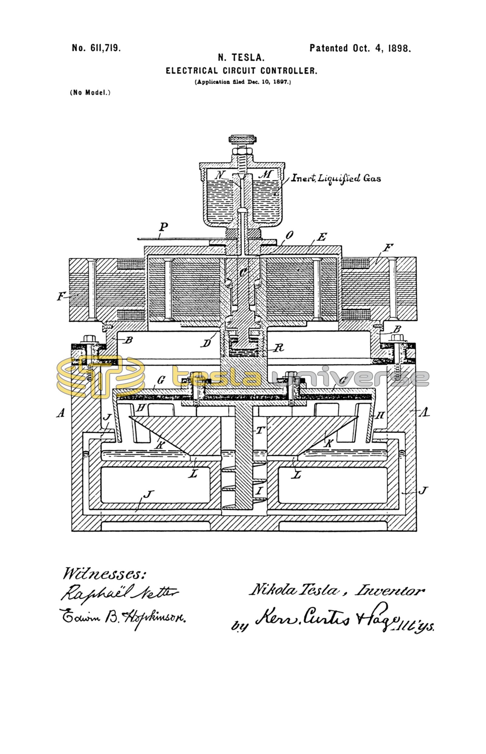
The details of this apparatus will be described by reference to the accompanying drawing, which is a vertical central section of the circuit-controller complete.
A is a receptacle, of iron, steel, or other proper material, with a head B, secured by a gas-tight insulating-joint. Within this receptacle is contained the circuit-controller, which, in so far as the main feature of my present invention is concerned, may be of any desired construction, but which, for the reason stated above, is of the special character shown. A spindle C is screwed or otherwise secured centrally in the head B, and on this is mounted on antifriction-bearings a body to which rotary motion may be imparted. The construction of the device in this particular and the means for imparting rotation to the said body may be greatly varied; but a convenient means for accomplishing this is to secure to the rotary sleeve D a laminated magnetic core E and place around the portion of the head B which contains it a core F, provided with coils and constituting the primary element of a motor capable of producing a rotary field of force which will produce a rapid rotation of the secondary element or core E. To the depending end of the sleeve D is secured a conductor G, usually in the form of a disk with downwardly-extending teeth or peripheral projections H. To the sleeve or the disk G is also attached, but insulated therefrom, a shaft T, having a spiral blade and extending down into a well or cylindrical recess in the bottom of the receptacle. One or more ducts or passages J lead from the bottom of this well to points near the path of the conducting-teeth H, so that by the rotation of the screw I a conducting fluid, which runs into the well from the receptacle, will be forced up through the duct or ducts, from which it issues in a jet or jets against the rotating conductor. To facilitate this operation, the well is surrounded by a flange K, containing passages L, which permit the conducting fluid to flow from the receptacle into the well, and having beveled sides which serve as a shield to deflect the fluid expelled from the ducts through the spaces in the conductor to the bottom of the receptacle.
M is any suitable reservoir communicating with the interior of the main receptacle and containing a liquefied gas, such as ammonia, which maintains a practically inert atmosphere under pressure in the receptacle.
Preferably, though mainly as a matter of convenience, the receptacle M is a metal cup with a hollow central stem N, the opening for the passage of gas being controlled by a screw-valve in the top of the cup. The said cup is screwed onto the end of the spindle C, through which is a passage O, leading into the interior of the receptacle A.
The receptacle A and the conducting fluid, which is generally mercury, being normally insulated from the head B and the parts attached and supported thereby, are connected to one part of the circuit to be controlled. The other circuit connection is made by a conductor P to any part of the head, so that when the core E and conductor G are rotated the circuit will be completed between the two insulated parts of the receptacle through the jet or jets of conducting fluid whenever they impinge upon the said conductor.
To insure a good electrical connection between the sleeve D and the spindle C, I provide in the former a small chamber R, which contains mercury, and into this the end of the spindle C extends.
The special advantages of this particular form of circuit-controller heretofore referred to will now more readily appear. The mass and weight of the rotating parts are greatly reduced and a very high speed of rotation obtained with small expenditure of energy. The power required to maintain the jets of conducting fluid is, moreover, very small.
Having, now described my invention, what I claim is—
1. The combination with a closed receptacle, of a circuit-controller contained therein and surrounded by an inert insulating medium under pressure.
2. The combination with a closed receptacle, of a circuit-controller contained therein and means for maintaining within said receptacle an inert atmosphere under pressure.
3. The combination with a closed receptacle, of a circuit-controller contained therein, and a vessel containing a liquefied inert gas, and communicating with the interior of the receptacle.
4. The combination with a circuit-controlling mechanism, one part or terminal of which is a conducting fluid, such as mercury, of a receptacle enclosing the same and means for maintaining an inert gas under pressure in the receptacle.
5. The combination with a conductor or series of conductors constituting one terminal of a circuit-controller, means for maintaining a stream or jet of conducting fluid as the other terminal with which the conductor makes intermittent contact, a closed receptacle containing the terminals, and means for maintaining an inert atmosphere under pressure in the receptacle.
6. A device for making and breaking an electric circuit comprising, in combination, means for maintaining a jet or stream of conducting fluid which constitutes one terminal, a conductor or conductors making intermittent contact with the jet and constituting the other terminal and a receptacle enclosing and excluding oxygen from the said terminals.
7. The combination with a receptacle, of a conductor or series of spaced conductors mounted therein, a motive device for rotating said conductors, one or more nozzles for directing a stream or jet of fluid against the conductor, and a force-pump in direct connection with the conductor for maintaining a circulation of conducting fluid contained in the receptacle through the nozzle or nozzles, the conductor and the fluid constituting respectively the terminals of a circuit-controller.
8. The combination of a casing, a conductor or series of spaced conductors mounted therein, a motor for rotating the same, one or more ducts or channels from a receptacle containing a conducting fluid and directed toward the conductors, and a screw operated by the motor for forcing the conducting fluid through the duct or ducts against the conductors, the conductors and the fluid constituting the terminals of an electric-circuit controller.
9. The combination with a receptacle containing a conducting fluid, of a conductor mounted within the receptacle, means for rotating the same, a screw rotating with the conductor and extending into a well in which the fluid collects, and a duct or ducts leading from the well to points from which the fluid will be directed against the rotating conductor.
10. The combination with the receptacle, of a spindle secured to its head or cover, a magnetic core mounted on the spindle within the receptacle, means for rotating said core, a conductor rotated by the core, and a pumping device, such as a screw rotated by the core and operating to maintain a jet or jets of conducting fluid, against the conductor, when in rotation.
NIKOLA TESLA.
M. LAWSON DYER,
G. W. MARTLING.