Plans
Build a Solid State Tesla Coil
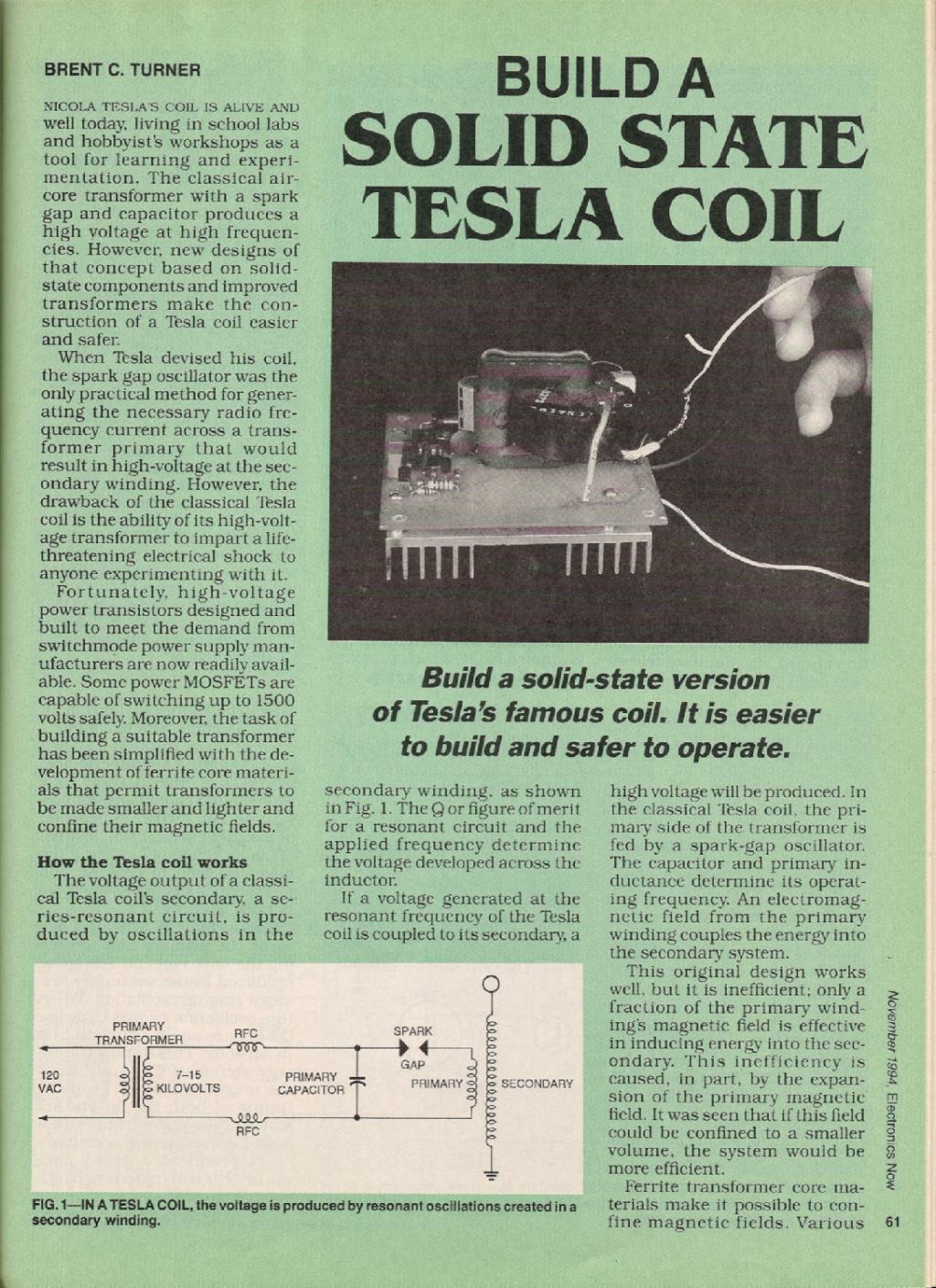
Build a solid-state version of Tesla's famous coil. It is easier to build and safer to operate.
Nikola Tesla's coil is alive and well today, living in school labs and hobbyist's workshops as a tool for learning and experimentation. The classical air-core transformer with a spark gap and capacitor produces a high voltage at high frequencies. However, new designs of that concept based on solid-state components and improved transformers make the construction of a Tesla coil easier and safer.
When Tesla devised his coil, the spark gap oscillator was the only practical method for generating the necessary radio frequency current across a transformer primary that would result in high-voltage at the secondary winding. However, the drawback of the classical Tesla coil is the ability of its high-voltage transformer to impart a life-threatening electrical shock to anyone experimenting with it.
Fortunately, high-voltage power transistors designed and built to meet the demand from switchmode power supply manufacturers are now readily available. Some power MOSFETs are capable of switching up to 1500 volts safely. Moreover, the task of building a suitable transformer has been simplified with the development of ferrite core materials that permit transformers to be made smaller and lighter and confine their magnetic fields.
How the Tesla coil works
The voltage output of a classical Tesla coil's secondary, a series-resonant circuit, is produced by oscillations in the secondary winding, as shown in Fig. 1. The Q or figure of merit for a resonant circuit and the applied frequency determine the voltage developed across the inductor.
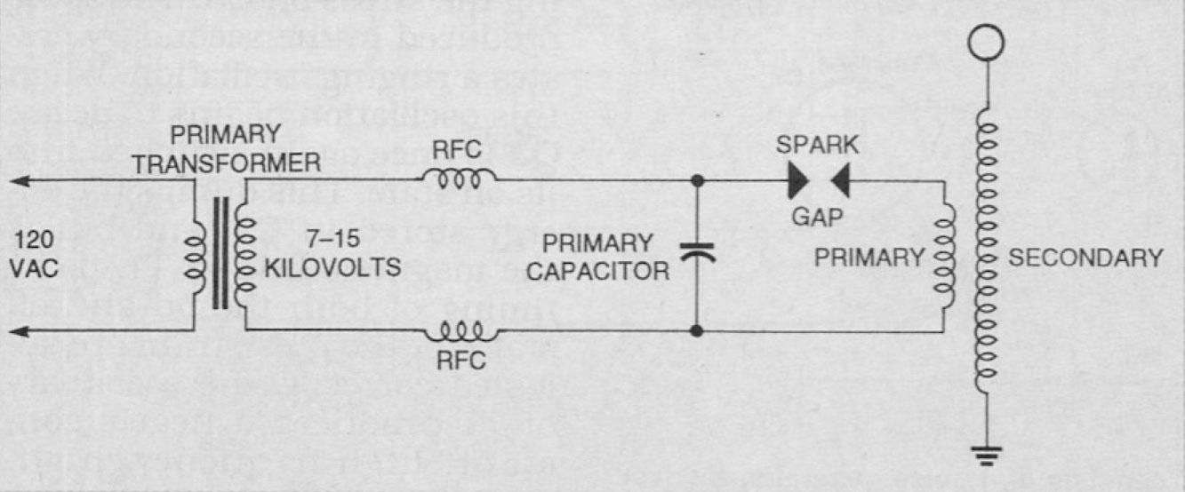
If a voltage generated at the resonant frequency of the Tesla coil is coupled to its secondary, a high voltage will be produced. In the classical Tesla coil, the primary side of the transformer is fed by a spark-gap oscillator. The capacitor and primary inductance determine its operating frequency. An electromagnetic field from the primary winding couples the energy into the secondary system.
This original design works well, but it is inefficient; only a fraction of the primary winding's magnetic field is effective in inducing energy into the secondary. This inefficiency is caused, in part, by the expansion of the primary magnetic field. It was seen that if this field could be confined to a smaller volume, the system would be more efficient.
Ferrite transformer core materials make it possible to confine magnetic fields. Various powdered compositions of ferric oxide and other metals such as nickel or cobalt are compressed and sintered to form solid cores. Their high resistance makes eddy current losses very low at high frequencies, and coupling efficiency is improved.
The operating principle of the primary system in the solid-state coil design discussed in this article differs from the principle of the classical spark-gap design. If a spike of energy is applied, the coil responds with an oscillating burst that decays with time, analogous to the ringing of a bell when struck by the clapper.
If there is no instant damping of the ringing, it will occur at the natural resonant frequency of the coil. A higher voltage output will be produced by a phenomenon known as Q factor multiplication.
The solid-state Tesla coil includes a stock, off-the-shelf, high-frequency pulse transformer. It is essentially the same as the transformer that you will find in the high-voltage generation circuit of a standard television set.
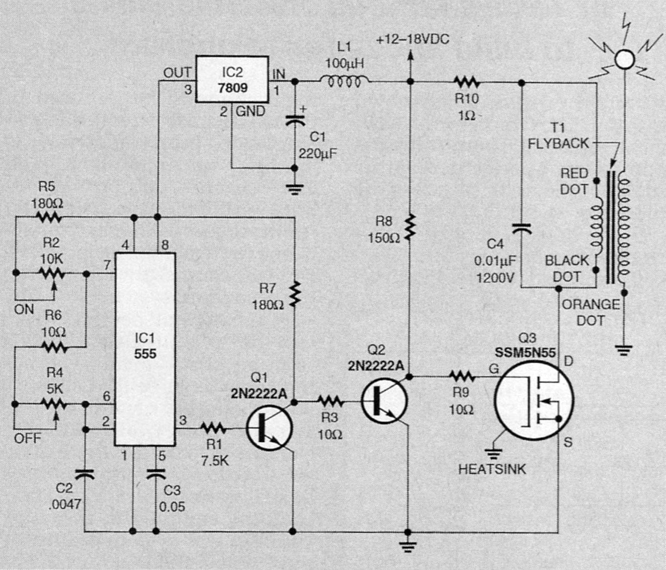
The coil circuit
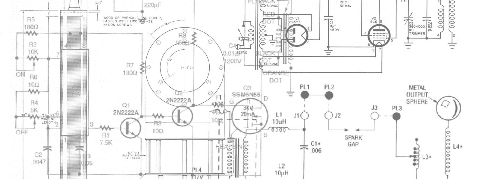
Refer to Fig. 2. The Tesla circuit consists of a pulse generator, a driver circuit, and a high-voltage transformer. The pulse generator, a 555 timer (lC1), is organized to run in its astable mode to generate a continuous pulse train. Resistors R1 and R2 determine the time duration that the output at pin 3 is off, while R3 and R4 along with R1 and R2 determine the on time. Inductor L1 and regulator IC2 provide a clean, stable power source for the timer.
Transistor Q1 acts as a buffer, effectively isolating IC1 from the highly capacitive load present on the gate of Q3. Resistor R6 determines the rise time based on the time constant developed by R6 and the inherent gate capacitance of Q3. Resistor R8 limits current so that excessive current will not damage T1's primary winding. Capacitor C5 absorbs some of the back EMF generated in T1's primary. Another function of C5 is to provide an extra kick to drive Q3 to an on state.
PARTS LIST
All resistors are 1/4-watt, 5%, unless noted.
R1 — 7500 ohms
R2 — 10,000 ohms, potentiometer
R3, R6, R9 — 10 ohms
R4 — 5000 ohms, potentiometer
R5 — 180 ohms
R7 — 180 ohms
R8 — 150 ohms, 1/2-watt
R10 — 1 ohm, 5 watts
Capacitors
C1 — 220 µF, 25 volts, electrolytic
C2 — 0.0047 µF, 50 volts, Polyester
C3 — 0.05 µF, 50 volts, Polyester
C4 — 0.01 µF, 1200 volts, Polyester
Semiconductors
IC1 — NE555 timer
IC2 — LM7809, + 9-volt regulator
Q1, Q2 — 2N2222 NPN transistor
Q3 — SSM5N55 FET transistor (Samsung or equivalent)
Other components
L1 — 100 µH choke (Radio Shack No. 273-102 or equivalent)
T1 — Flyback transformer (PennTran No. 1-017-5372 — or equivalent, provided that the high-voltage rectifier is not embedded within the transformer)
Miscellaneous: Heatsink for Q3, eight-pin socket for IC1, wire, high-voltage wire, perforated construction board.
The pulse waveform from IC1 is applied to Q1, which provides the high current necessary to offset the high capacitance of Q3. When Q3 starts to conduct, current flows through T1's primary, building a magnetic field in the core. After a short time interval, the core saturates, preventing any further generation of magnetic flux. Prior to this, Q3 is switched off, causing the magnetic field to collapse and producing a sharp voltage spike in both windings.
Capacitor C5 partially absorbs the primary EMF, reducing the stress on Q3. The spike produced in the secondary creates a ringing oscillation. When this oscillation begins to decay, Q3 is once again switched into its on state. This dumps the energy stored in C5, and builds the magnetic field in T1. If the timing of both the on and off states of the pulse train are adjusted correctly, the secondary of T1 produces a nearly constant, high-frequency, high-voltage current.
Construction and adjustment
Begin construction with the pulse generator. It can be built on a small piece of perforated construction board. After installing all components, verify all connections, and apply 12 volts to the circuit. Verify that a pulse train is present at pin 3 of IC1 with an oscilloscope. While examining the waveform at pin 3, determine that both potentiometers (R2 and R4) function correctly by changing both the on and off time periods.
If that circuit works satisfactorily, turn off the power, insert the components, and wire the remainder of the circuit. Leave the connections to the primary winding of T1 open. Apply power and examine the waveform on the collector of Q1 with an oscilloscope. Verify that the waveform is the same as that present at pin 3 of IC1, but inverted. (There might be slight rounding of the leading edges due to the capacitive effects of Q3.) Temporarily connect a 10-ohm, 10-watt resistor in place of the primary of T1. Verify that Q3 is switching the current on and off in sync with the signal at pin 3 of IC1.
If the circuit appears to be operating correctly, adjust R4 to produce an off time of about 10 microseconds (µs), and adjust R2 for an on time of 60 to 70 µs. Remove power and the temporary 10-ohm resistor. Connect T1 to the circuit and apply power, observing the current that the circuit draws. With all circuitry operating correctly, some corona should be visible on the high-voltage lead of T1, accompanied by a slight hissing noise. (There might also be a faint whistle from T1.)
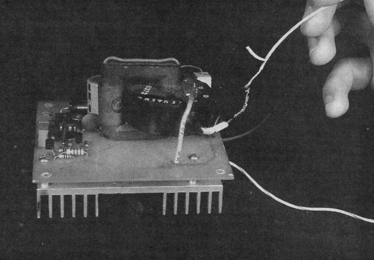
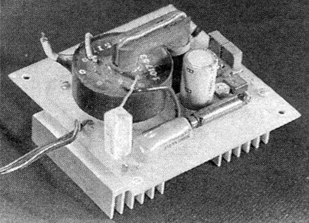
Attempt to create an arc from the high-voltage lead of T1 with a grounded lead. The voltage should be high enough to strike an arc of over 1/2 inch. By adjusting R4, maximum voltage output can be obtained. Similarly, small adjustments to R2 will also affect output power. Figure 3 is a photograph of the author's prototype.
Applications
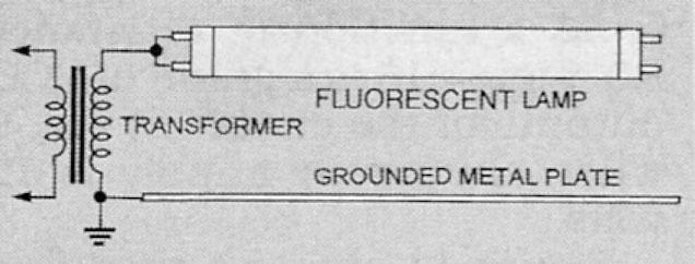
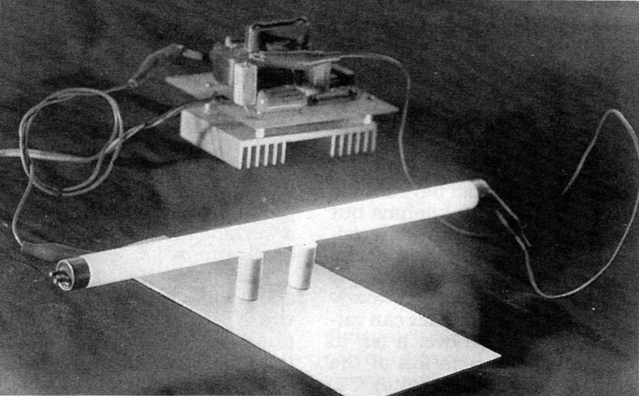
Many interesting experiments can be performed with this circuit. By attaching a small brass drawer knob to the high-voltage lead, sufficient RF energy will be radiated to light low-wattage fluorescent lamps up to several inches away, without wires (see Figs. 4 and 5).
The solid-state Tesla coil has enough power to drive decorative plasma lamps. By adjusting R2 and R4, various discharge patterns can be obtained. A modulating voltage on pin 5 of IC1 will modulate the output and create more interesting visual effects.
The low-current output of the solid-state Tesla coil is not an extreme hazard to healthy adults. However, the high-voltage output should still be treated with respect. The shock can be dangerous to people with heart problems, and the arc can easily start a fire.