Plans
Miniature Tesla Coil
Miniature in size only, this physics classroom project packs 60,000 volts of power at 500,000 cycles per second. Yet it’s safe!
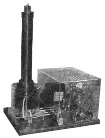
You can make spectacular demonstrations with this Tesla coil (Fig. 1) while you’re studying the effects of high frequency current. That’s just what Nicola Tesla did with his famous induction coil beck in 1892. Although you will be experimenting with 60,000 volts, it is quite harmless because of its high frequency of 500,000 cycles per second. Currents of high frequencies travel over conductor surfaces only, so that contact with it results in the current going over your skin to a ground, thus avoiding possible injury to internal organs.
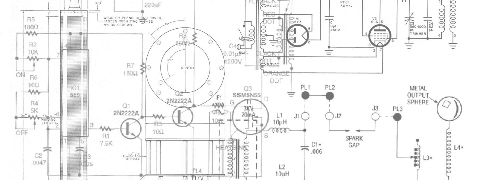
The coil uses only one oscillator tube which is enclosed with the other power-supply components in a transparent plastic housing for safety and as a showcase. The coil is mounted on a transparent plastic base with a clear plastic cylinder enclosing the primary section of the coil for protection from its high voltage (Fig. 2). Careful attention has been given to insulation of the coil and all wiring so that leakage has been reduced to a minimum.
The tube used is the Hytron 5514 transmitting type which operates on about 175 milliamperes plate current maximum, and the plate voltage is supplied at 1,200 volts from s Stancor PC-8414 power transformer with 200 milliamps. max. rating. Except for the transformer’s primary and 2,000-volt leads, all other leads are taped and are not used. Only high-grade mica transmitting capacitors are used (poor quality capacitors will break down quickly under the high voltage) and the filament transformer is a Stancor P-5015, having a center-tapped 7,5-volt winding to supply the tube filament. The entire unit is secured to a hardwood-veneer plywood base.
First get all the materials required (see Materials List) and then make the unit base from Ľ-in. birch, walnut or mahogany-veneer plywood (Fig. 3). Sand the edges and top, and apply oil stain of the color desired. Let stand 5 minutes and wipe off surplus with a cloth. After stain dries, apply two coats of white shellac, cut with an equal amount of wood alcohol, and sand each coat lightly with 6-0 paper. Finish with several coats of paste wax.
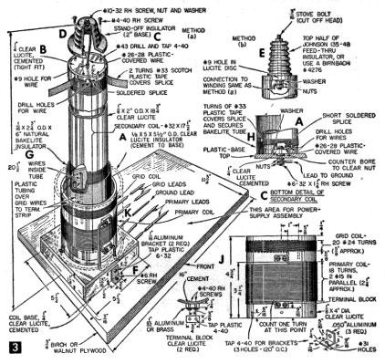
Make the secondary coil from a clear Lucite tube (Fig. 3-A.) Chuck the tube in a lathe and, at slow speed, wind s single, close layer of #32 Formvar magnet wire, keeping start and finish ends ˝-in. from ends of tube. Drill two small holes at start and finish points for wire ends to pass through for soldered connections to short, insulated flexible leads (Fig. 3-A and H). Secure winding temporarily around the start and finish with adhesive tape until the connections have been soldered. Winding must be done carefully with no overlapping of turns or kinks. To make the connections, use short lengths of plastic-insulated #26-28 stranded wire; bare ends and pass through one hole from inside of tube; pass winding end through other hole and out with flexible lead; twist into a short, pigtail splice on outside of tube and solder, using resin-core type (Fig. 3-A and H). To solder, Formvar insulation must first be removed. This is best done with a lighted match held under the wire for a few seconds. Then, use a piece of fine sandpaper to clean the end to the bare copper. Handle carefully as this fine wire breaks easily. After soldering, bend splice against tube and use two turns of plastic tape around last few turns of wire and over splice to hold and insulate it. The exact number of turns in this secondary coil is not important so you need not count them, but if wound correctly, there should be about 1,800 turns.
Next, make two discs from clear Lucite flat stock, finished to fit tightly into tube ends. Drill a #9 hole and tap three 4-40 holes in top disc as in Fig. 3-B, for attaching stand-off insulator. In method “a” (Fig. 3-B), pass flexible lead through hole in disc and attach disc to tube with Lucite cement. Method “b” requires a 3/16-in. stove-bolt assembly to which flexible lead is attached with nuts. Cover nuts with several coats of varnish or high voltage “dope” to prevent corona discharge here; then, cement. Drill a #27 hole in the center of the bottom disc for a 6-32 x 1Ľ-in. rh brass screw and nut. Connect the flexible lead under head of this screw. A ground-wire is later connected to this screw under the base top.
The top insulator is of brown, glazed porcelain and has a base about 2-in. dia. (Fig. 3-D), commonly called a beehive or stand-off type for supporting high-voltage wire above a surface. The one we used was discovered on the surplus counter of an electronics-supply store. If you cannot find one of a size to fit the end of the tube, use the top half of a feed-through porcelain insulator (method “b” Fig. 3-E). With the secondary-coil assembly completed, apply four coats of Bakelite resin spar varnish to the coil in even, smooth coats, allowing each coat to dry thoroughly. While the varnish is drying, you can make up the coil base (Fig. 3-F).
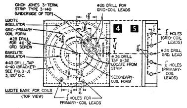
Cut the Lucite base parts according to dimensions in Materials List and finish edges smooth and square. In the top, drill all the holes indicated in Fig. 4, with the exception of the 3 bracket holes; these are best drilled after brackets have been attached to primary coil form (Fig. 3-J). In the right side piece, drill holes as in Fig. 5 for the plastic-insulated leads (Fig. 3-K). To cement the base parts together, pour a small quantity of the cement on a sheet of flat glass and place plastic edge in puddle for about 20-30 sec, sliding edge around to make sure all edge surfaces have contacted cement. Then, place edge in position against piece to be joined, sliding edge back and forth a few times. Then, apply pressure with clamps or weights for several hours. Rehardening takes a few hours. When cement has hardened, attach secondary-coil form to top of base with pre-set 6-32 brass screw, securing as in Fig. 3-H.
Now, wind the primary and grid coil on a piece of clear Lucite tubing 4-in. dia. (Fig. 3-J and K). The primary winding requires 18 turns of two #15 Formvar wires in parallel (two wires for each turn), ends of wires formed into loops to fit over the terminal screws tapped into two clear Lucite blocks cemented to tube - or you can use one #12 Formvar magnet wire (same number of turns). The grid winding consists of 20 turns of #24 Formvar wire, ends left long enough to be carried through drilled holes in tubing, down inside of tube and through holes in base to terminal-strip screws (as in Fig. 4). Cover these leads from inside of coil form to terminal strip with plastic spaghetti-type tubing. Don’t forget to clean Formvar wire wherever connections are made. Assembly completed, apply Bakelite resin spar varnish to coils as with secondary coil. Now, from a piece of Bakelite tubing, cut an insulator sleeve (Fig. 3-G), slip over secondary-coil form for a tight fit over form’s base which has been enlarged with turns of plastic tape (Fig. 3-H). When grid-primary coils have dried, slip form over secondary coil and attach to Lucite base top with 3 angle brackets (Fig. 3-I).
Use about 15-in. long flexible, #16 stranded wire having 5,000-volt or higher plastic insulation for the primary coil; connect to screws on terminal blocks and thread through base-top holes, under base and out of side (Fig. 5). Use about 15-in. long flexible, #16 stranded wire having 1,000-volt plastic insulation for the grid leads; connect to screws of terminal strip (under base) and out through base side. Use 15-in. long flexible, #16 stranded wire with regular plastic insulation for ground lead, connecting with a washer and nut to secondary coil screw under base top and out through center hole in base side (Figs. 3-C and 5). Now attach coil-base assembly to plywood base with two angle brackets and #6 rh wood screws (Fig.3-F).
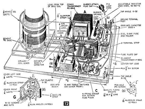
The next step is to install the power-supply components and its protective plastic cover. First cut and drill the Ľ x 1 ˝ x 10 11/16 in. Bakelite strip and Ľ x 8 x 8Ľ in. Lucite front piece as detailed in 13A. Then attach both strip and front pieces to plywood base with aluminum angles as in Fig. 12-Ga. With some narrow masking tape, outline the locations of the cover-side and back on the plywood base to give you an idea of clearances needed when arranging and attaching the various power components to the base (Fig. 12).
The Stancor PC-8414 power transformer is used as a plate transformer by covering the ends of the unwanted leads with tape and tucking them neatly under the transformer. Use the two black primary and the two plain red leads which will give you 1,200 volts. Cut four ˝ in. long spacers from Ľ in. pipe and place under the transformer feet to clear the leads (Fig. 12-A). Connect components with at least #16 ga. plastic-covered stranded wire. Use solder or solderless connecting lugs on all wire ends connecting to screw-nut terminals and solder all other connections. Bring the line cord through a rubber grommet mounted on an aluminum angle bracket, and knot the cord to relieve strain (Fig. 12-D). Attach a surface-mount fuse holder and a 5-amp., 3AG Slo-Blo glass fuse and connect in series with one side of the line. In use, the Tesla coil will draw about 4 amps.
Mount the adjustable grid resistor over the .0005 mfd. capacitor with an aluminum bracket attached to one terminal, using a #6-32 rh screw and nut. Solder a flexible lead to the adjusting strap and connect other end to other capacitor terminal (Fig. 12-D). Mount a ground terminal post on an aluminum angle bracket as in Fig. 12-E. A ground wire from post to a water pipe, if practical, is best but not essential. Use a 2-term. barrier strip, located as in Fig. 12-F for a convenient connection point for all wiring going to ground (one pair of terminals not used). Two .0015 mfd. capacitors across the coil primary (Fig. 12) are shown connected in parallel. One .003 mfd. capacitor can be used instead, if available. The Hytron-tube plate cap of porcelain is connected to one of the above capacitor terminals exactly as in Fig. 12. Values given for the capacitors must be closely followed, especially the two in parallel (each .0015 mfd.). With the specified number of turns in the primary coil, as was described earlier, the value of .003 mfd. brings the coil into proper resonance, a maximum discharge of about 4-5 in. being obtained from the top of the secondary coil. The 4-in. dia. of the primary coil is a must; otherwise the inductance would be affected, requiring a different capacitor value.
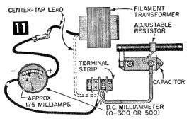
The filament transformer is a Stancor P-5015, located as in Fig. 12-B. Use two 5/16 O.D. x 5/8 in. long Bakelite tube spacers under the Hytron-tube socket to clear the terminals, only three of which are used (Fig. 12-C). With all connections securely attached, set the adjustable grid resistor for about 1,500 to 1,800 ohms with an ohmmeter and then use a d.c. milliammeter with a scale of from 0-300 or 500. Disconnect filament transformer center-tap lead from terminal strip (Figs. 12 and 11), and connect ammeter in series (meter “plus” terminal connected to transformer lead) as in Figs. 11 and 14. Plug in line cord and turn on filament switch (Fig. 12-H). Allow about half a minute for tube warm up and then throw on plate switch (Fig. 12-J). The meter should show a reading of about 175 milliamperes, maximum capacity of tube (slightly under is better to prevent overheating of tube-plate element). There should also be a good brush discharge from the top of the secondary coil - about 4 in. If the reading is low, shut off power and adjust grid resistor for less resistance; if high, increase resistance. Always make certain line plug is disconnected from power source before attempting any adjustments or work around the connections. The voltage is high and dangerous. Don’t become careless! In the test (Fig. 14), the meter read approximately 175 ma. after resistor had been adjusted. A 4˝-in. high discharge at the secondary-coil tip resulted. In use the Hytron-tube plate may glow dull red after 10-15 minutes of constant operation. This is normal. If the plate gets any brighter, reduce the grid drive by cutting in more resistance, or else turn unit off for a short time to allow tube to cool.
Failure to get a brush discharge as described may be due to wrong connections, defective capacitors, possible wrong capacitor values, or an error in number of winding turns in primary and/or grid coils. Coils must all be wound in the same direction without splices or defective spots over their entire length. In some cases due to the accepted tolerance of 5% plus or minus in capacitor marked values, the capacitors used across the coil primary may not be exactly correct for resonance and others may have to be tried. Try adding another capacitor of about .001 mfd. in parallel with the other two. This combined value of .004 may do the trick. Possibly a little less capacitance is needed, so try one of .001 in place of one of the .0015. A coil form not of the diameter specified also will cause failure.
To keep the cost of the coil down, the use of surplus mica transmitting capacitors is suggested. If bought through normal supply dealers, these units cost from $7.41 to $10.17 each. Surplus capacitors of this type usually sell for about $1.50 to $2.25, depending on the voltage rating. The following surplus electronic supply dealers might be tried for the desired values. Specify mica transmitting type of Cornell Dubilier, Sprague, Sangamo or similar high grade make.
Standard Radio, 86 Franklin St., New York 13, N. Y., reports that they have .003 mfd. 3000 volt, .0018 mfd. 5000 volt (can be used in place of .0015 mfd.), .003 mfd. 5000 volt, .0005 mfd. 3000 volt.
Electro Sales, 50 Eastern Avenue, Boston, Mass., has several values but not quoted.
Enclosing the high-voltage components to prevent accidental shock is a must. Clear Lucite is ideal for this purpose since it serves as good insulation and as a showcase, particularly for classroom instruction on the “why” of the various parts. For home use, if the experimenter has a limited budget, ¼ or ½-in. fir plywood can be used as a substitute for the plastic enclosure with, of course, adequate ventilating holes.
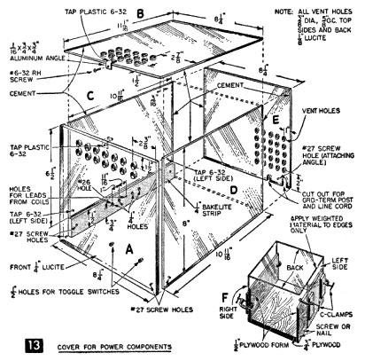
Cut four pieces of ⅛-in. clear Lucite (top, two sides and back) to dimensions shown in Fig. 13, drilling all holes required and making sure edges are square and true. Then, cement back to sides as described earlier. A cementing jig (Fig. 13-F) will facilitate assembly. Apply pressure with weighted material immediately after applying cement and let dry for several hours. Then, cement top to sides and back, again using adequate pressure. Attach an aluminum angle to top with a #6-32 rh screw (Fig. 13-B) and cover-assembly top to front with a #6-32 rh screw (Fig. 13-A). Attach left side (which rests on Bakelite strip) to strip with two #6-32 rh screws, one each front and back (Fig. 12-Ga). Finally, attach cover assembly to plywood base with two aluminum angles and #6-32 rh screws located at right side and back between line cord and terminal post (Figs. 12-Eb, and 14). To prevent accidental shock from the primary coil, cement to coil base a ⅛” x 5” x 5½” O.D. clear Lucite cylinder (Fig. 3-A) as in Fig. 12.
Interesting and Instructive Experiments are possible with this Tesla coil. Since energy from the coil radiates over a considerable distance, causing radio and TV interference, experiment when you are unlikely to annoy neighbors.
To demonstrate that high-frequency current cannot cause a shock even though the voltage is high, move your hand back and forth about 4-5 in. from the top terminal. The charge will travel to your hand. Keep your hand moving, however, and for only a short time, as the tiny points of discharge are quite hot and can cause burns. The reason there is no shock is that high-frequency current travels only over the skin surface. A coin held in the fingers is perhaps the safest method, there being less danger of burns.
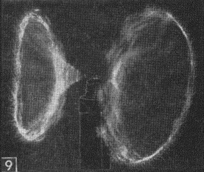
Another demonstration of the “skin” travel of high-frequency currents is to attach a 12-in. piece of fine nichrome or steel piano wire (about .007-.008 in.) on the coil terminal by twisting it around the screw at the center of the wire. Straighten out the wire to a horizontal position, and use an additional nut on the terminal screw to hold the wire in place. When power is turned on, a pair of brilliant arcs of lavender color will result as ends of the wire rotate at high speed. Examination of the wire will reveal that tiny discharges are breaking out all along the wire (Fig. 9). High-frequency current travels only over the surface of conductors and since the fine wire does not have adequate surface area, the discharges leap to the surrounding air. The rotation is probably due to the whipping or snapping effect resulting from applying high energy to an inadequate conductor.
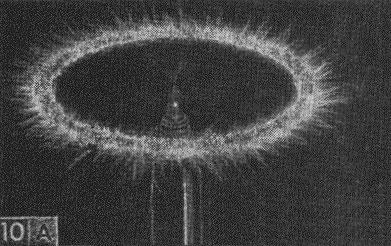
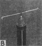
The “spinner” or “jet” rotor is a favorite Tesla-coil experiment. In the top of a “dome” nut to fit the terminal screw, drill a hole to take a large needle broken off to shorten it. Solder needle, point up, in the hole. In a small brass piece, drill a small hole to receive needle point and solder to this piece a #16 gage copper wire 8 in. long and centered on the brass piece for good balance. Cover each arm of wire with plastic tubing, leaving about ⅛ in. of ends bare. Bend ends and file them to points (Fig. 10 B). The rotor should turn with a minimum of friction. When power is turned on, the rotor will spin at high speed producing a ring of lavender sparks (Fig. 10A). The rotation is due to the thrust caused by the density of the charge at the pointed tips, producing an electrical “wind” effect. The rotor will start slowly and gradually gain speed, dependent somewhat on the amount of friction at the pivot.
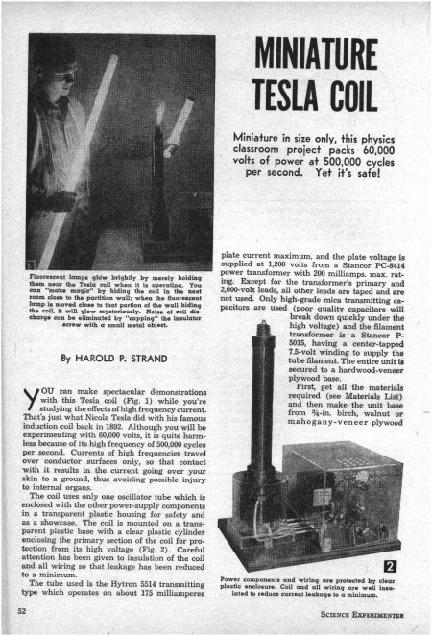
Fluorescent lamps held in the hand will light almost to full brilliance when near the discharge (as shown in Fig. 1).
Because the field of energy surrounding the coil extends for some distance which you can test by walking slowly away from the coil, the fluorescent tubes tend to grow dimmer and finally fade out. If you want to mystify your friends, place the coil near a wall, turn it on and go to an adjoining room, holding a fluorescent tube near the wall and coil. You’ll get sufficient light to read by. The mystification is even greater if you cap the coil terminal with a cup-shaped piece of metal. This eliminates the discharge and noise but does not affect this or some other experiments. Fluorescent lamps light up because the high-frequency current activates the phosphors inside the tube.
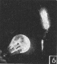
If you hold a clear 150-watt light bulb near the coil, the bulb will light up with a strange color combination (Fig. 6). This is thought to be due to the high-frequency energy ionizing the gas in the bulb. (Tesla noted the strange effect of flames inside a light bulb).
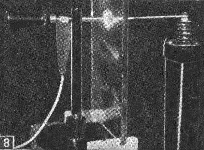
To demonstrate the fact that high-frequency, high-voltage current passes readily through material considered good insulation, make the experiment shown in Fig. 8. It consists of a stand fitted with an adjustable rod and handle to which a clip lead is attached from the coil ground terminal. A short piece of ⅛ in. dia. wire is attached to the discharge terminal and a piece of ¼-in. plate glass is supported between the electrodes. Adjust the gap distance to about ½-¾ in. and turn on the power. A discharge will take place in the gap as though no insulation existed. Try pieces of plastic, Bakelite and the like to observe how effective various insulation materials might be. You can widen the gap to a point where no discharge will occur except a small corona from end of wire attached to terminal, demonstrating that some insulating properties are present.
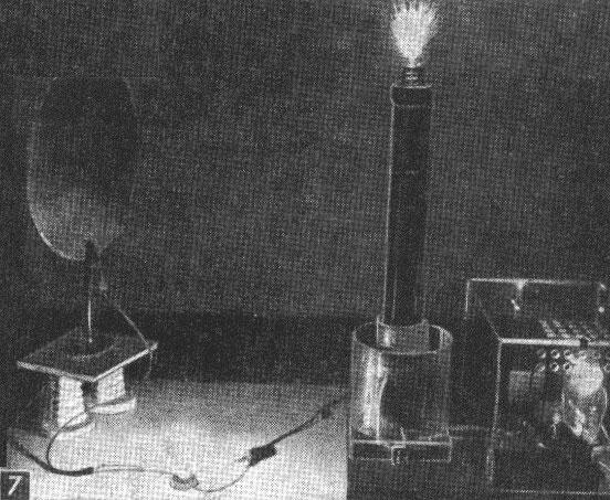
Fig. 7 illustrates Tesla’s theory concerning the transmission of power from a distance to light buildings without using conductors. He built a tall transmission tower and did actually prove his theory with a large coil. But the results proved to be commercially impractical and the project was abandoned. To demonstrate, attach a 12 in. dia. disc of sheet aluminum on a well-insulated stand and place it about 2 ft. away from the coil. Attach a clip lead to the aluminum and connect this to one side of a 125-v. 6-watt lamp. Connect other side of lamp to the ground terminal post of the coil unit. When power is turned on the lamp lights to full candle-power (Fig. 7), proving that electrical energy is being transmitted through the air. If the disc is moved closer, say 1 ft. away from the coil, the lamp will increase in brightness to a point where it may burn out. Moving the disc farther away decreases the brightness, since there is less energy in concentrated form, or is being dissipated in all directions. A high-resistance voltmeter (20,000 ohms per volt) can be tried in place of the lamp to register approximate voltages at varying distances, however, ordinary instruments are not usually very accurate on high frequency.
If you are interested in Tesla-coil experimentation but leery of construction, assembled models are available. Edmund Scientific, Barrington, N. J. 08007, offers a 15,000-volt model (Cat. #70,301) for $44 ppd. An instruction book that comes with it features 21 experiments.
Materials List - Miniature Tesla Coil
| 1 pc | ¾” x 11¾” x 16” oak. walnut or mahogany-veneer ply-wood for unit base |
| Clear Lucite Sheet | |
| 1 pc | ¼” x 5½” x 5½” for coil-base top |
| 2 pcs | ¼” x 1” x 5½” for coil-base front and back |
| 2 pcs | ¼” x 1” x 5” for coil-base sides |
| 1 pc | ¼” x 8” x 8¼” for power-supply cover front |
| 1 pc | ⅛” x 8¼” x 11¼” for power-supply cover top |
| 1 pc | ⅛” x 8” x 8¼” for power-supply cover back |
| 1 pc | ⅛” x 8” x 10 11/16” for power-supply cover right side |
| 1 pc | ½” x 6½” x 10 11/16” for power-supply cover left side |
| 2 pcs | ¼” x ⅜” x ¾” for terminal blocks |
| 2 pcs | ¼” x 2½” 2½” for secondary-coil-form top and bottom |
| Clear Lucite Tubing | |
| 1 pc | ⅛” x 2” o.d. x 18¾” for secondary-coil form |
| 1 pc | ⅛” x 4” o.d. x 4¾” for grid-primary-coil form |
| 1 pc | ⅛” x 5” x 5½”o.d. for primary-coil insulator |
| Natural Bakelite | |
| 1 pc | tubing, 11/16” x 2¾” o.d. x 6” for secondary-coil insulator |
| 1 pc | ¼” x 1½” x 10 11/16” for power-supply cover wire entrance |
| 1 pt | Lucite cement |
| (above products can be supplied by The Forest Products Co., Inc., 131 Portland St., Cambridge, Mass.) | |
| Magnet Wire | |
| ½ lb (approx) | #15 Fomvar (two lengths) or, #12 Formvar (1 length) for primary coil (try motor-rewind shops) |
| 2 oz (approx) | #24 Formvar for grid coil |
| ½ lb (approx) | #32 Formvar for secondary coil (#24 and #32 Formvar can be supplied by Lafayette Radio in 1-lb. spools) |
| Electronic Components | |
| 1 | porcelain insulator, beehive or stand-off type, round base 2” dia. (approx) 3 attaching holes #8 or 10 screw bolt or top-half Johnson 135-48 feed-thru insulator, or 8irm-bach #4276 |
| 1 | Stancor power transformer, PC-8414 |
| 1 | Stancor filament transformer, P-5015 |
| 2 | toggle switches, 6-amps, at 125 volts |
| 1 | tube-plate cap Millen 36001 or equivalent, 1/16” size |
| 1 | Cinch Jones 2-terminal strip, type 2-141 |
| 1 | Cinch Jones 3-terminal strip, type 3-140 |
| 1 | adjustable ohmite resistor, 2,500 ohms, 50 watts |
| 1 | fuse, 3 AG Slo-blo, 5 amp. |
| 1 | fuse holder, surface mount, type 357001 |
| 1 | rubber grommet for ⅜”-hole chassis, ¼” entrance hole |
| 1 | binding post, 5-way to take banana plug, wires, etc. ground terminal |
| 1 | 7-ft rubber or plastic covered #18 flat parallel lamp cord attachment plug cap for standard wall outlet |
| (above can be supplied by Lafayette Radio, 111 Jericho Turnpike, Syosset, L. I., N. Y.) | |
| 6 ft (approx) | #16 stranded wire, plastic insulation for 5,000 volts or better (Teflon insulation) for primary coil |
| 3 ft (approx) | #16 stranded wire, plastic insulation for 1,000 volts, type SRIR plastic hook-up wire for grid coil |
| 3 ft (approx) | #18 stranded wire, regular plastic insulation for grid wire |
| 1 | Hytron transmitting tube, #5514 |
| 1 | 4-prong, steatite or ceramic wafer-type tube socket |
| (above wire, tube and socket can be supplied by Cramer Electronics, Inc. 811 Boylston St., Boston Mass.) | |
| Capacitors (mica transmitting, Bakelite enclosed) Cornell-Dubilier or equivalent quality | |
| 1 | .003 mfd., 3,000 volts |
| 2 | .0015 mfd., 5,000 volts |
| 1 | .0005 mfd., 3,000 volts |
| Miscellaneous | |
| 13 | #4-40 rh machine screws |
| 17 | #6-32 rh machine screws |
| 1 | #10-32 rh machine screws |
| 10 | #6 rh wood screws |
| nuts, washers, terminal lugs, small pieces of sheet aluminum for brackets, stain, shellac, Bakelite resin spar varnish, resin-core solder, etc. |