Nikola Tesla Articles
The Tesla Power Wave (1899-1991)
Ron Kovac built a working model of Tesla’s 1899 Colorado Springs transmitter to investigate the Power Wave. This paper explains his simulation of Tesla’s experiments and the results.
Introduction
In the winter of 1899 in Colorado Springs, Colorado, a man named Nikola Tesla constructed a laboratory and a device to generate and test powerful electromagnetic waves. So peculiar were the frequencies and duration of these waves that, once generated, they would encircle the earth and reinforce subsequent waves generated an instant later by the same machine. Each successive power pulse would add its increment of energy to the previous pulses until the cumulative power total was very great. This power is currently viewed as accumulated in the resonant cavity between the ionosphere and the ground. The cavity was described by W. O. Schumann and is now named the Schumann Cavity. (3) So great was the power accumulated, Tesla claimed that people anywhere could simply reach up and get it from the total power for work or transportation. To obtain the power one needed an antenna device for reaching up - something smaller and more portable than the wave generator itself.
I believe that Power Wave generation for earth resonance and the convenient long distance reception of this power required that the Power Wave be sinusoidal and of a combined high and low frequency. This wave shape was possible with Tesla’s 1899 equipment.
Early photographs and notes of Tesla’s Colorado Springs work confirm that he had the capability to generate the necessary wave forms built into his lab.
Engineers and scientists previously argued that the design of the 1899 equipment as described in Tesla’s lab notes would only oscillate at a frequency much too high to resonate the earth cavity.
This holds true for the dimensions mentioned in Tesla’s own description. There exists, however, a wealth of literature including Tesla’s letters to New York and his Colorado Springs lab notes, which builds a conclusive case for the existence of an 1899 earth resonator, the first oscilloscope, and the first high voltage/high frequency rectifier.
To recreate Tesla’s experiment on a small scale, I built and tested a working model which generates the proper wave formation using the 1899 design. My model is available for demonstration.
Creating Wave Forms
Tesla’s Colorado Springs laboratory and supporting equipment were constructed to create a very specific wave form. I duplicated this wave form using a small working model and modern oscilloscopes. The power level of the Tesla waves of 1899 was very large. These waves differ from EMF, ELF, and radio waves in that they are magnitudes of ten greater in power. The machine I built was constructed to imitate Tesla’s method of 1899. This device successfully generates the needed wave shape. By using Tesla’s lab notes and letters I was able to construct a lab model similar to Tesla’s Power Wave device. To prevent confusion with EMF, ELF, and radio waves, the Tesla wave of 1899 will be called the Power Wave.
The Required Wave Shape
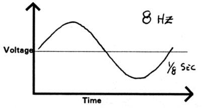
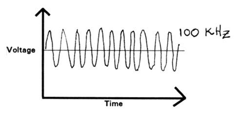
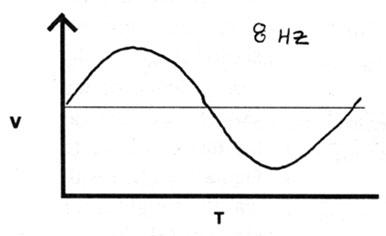
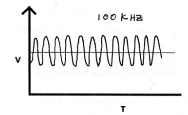
It has been the experience of previous researchers such as W. O. Schumann and others (3) that the 8 Hz range of frequency is best for waves required to travel around the world in the Schumann Cavity. Figure 1 is a graph of this part of the wave. Tesla’s Power Wave receiving devices were designed to activate at a much higher frequency (2) (Figure 2), perhaps 60 kHz to 100 kHz, since a much smaller antenna and tuning coil are needed for these higher frequencies than for receiving the 6 Hz or 8 Hz frequency.
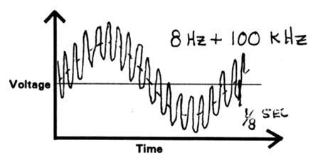
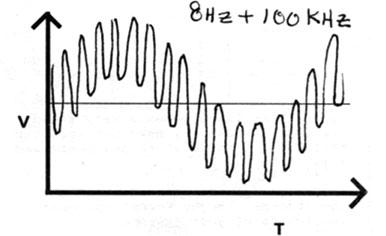
This higher frequency is represented in Figure 3 as the second required frequency of the Power Wave. I believe that Tesla was constructing equipment which combined the earth resonance facility of the 8 Hz range with the practical reception afforded by a 60 kHz frequency. This is not unlike audio music signals put on top of a regular AM broadcast carrier wave. The 8 Hz and 60 kHz transmitted together form the Power Wave, and would appear on an oscilloscope connected to a broadband antenna as shown in Figure 4.
Construction of a Working Model
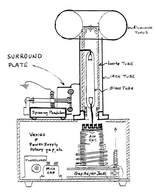
I have built a Power Wave transmitter model using an ordinary air coil transformer with an induction coil power supply as shown in Figure 5. The high voltage side of the air coil is directly coupled with the bottom electrode of a hydrogen-filled glass tube having its upper electrode connected to an iron antenna. Inside this glass tube, partially evacuated, are drops of mercury. The iron antenna encloses the glass tube. At the top of the iron antenna I attached an aluminum toroid to increase antenna capacity.
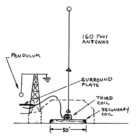
To modulate the Power Wave, I attached a mechanical pendulum to the bottom of the iron antenna. The pendulum part is grounded, but the surround plate is attached to the antenna. The surround plate is best explained in Figure 5, the construction diagram.
The speed adjust of the motor spinning the pendulum determines the low frequency of the Power Wave. The vibrator adjust of the spark coil, which is a feed-back chatter relay with variable voltage, determines the high frequency. The high frequency is also determined by the air coil parameters.
I selected a low power level design for the model Power Wave generator to permit the use of delicate modern test equipment for wave monitoring without danger to the test equipment. Operating model receivers requires using a higher power transformer in the primary circuit, which I plan to do.
How Did Tesla Create the Power Wave?
The air coil part of Tesla’s device is well-documented and accepted, so I will not go into detail on that aspect of the experiment. (7)
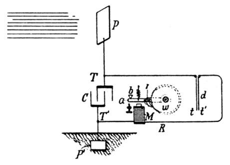
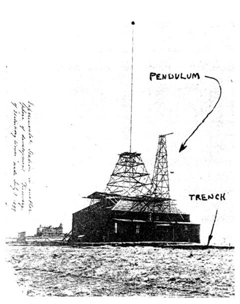
The pendulum modulator for Tesla’s transmitter can be seen in Photo 1 on the right side of his laboratory. (7) This pendulum could be adjusted from six seconds to any faster frequency by shortening the length of the pendulum.
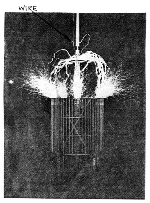
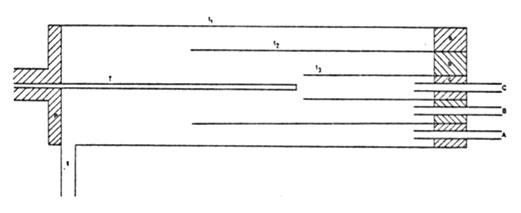
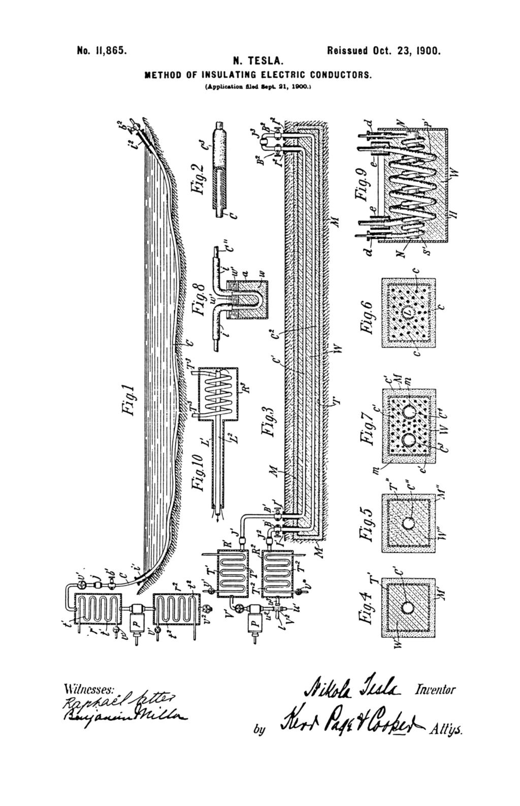
Figure 6 shows the path of a heavy gauge wire connecting the surround plate to the top of Tesla’s secondary coil. In Photo 2, taken inside the lab, you can see the same wire dropping from the ceiling. This photo shows Tesla’s third coil, which in Figure 6 is the small coil at the center under the antenna.
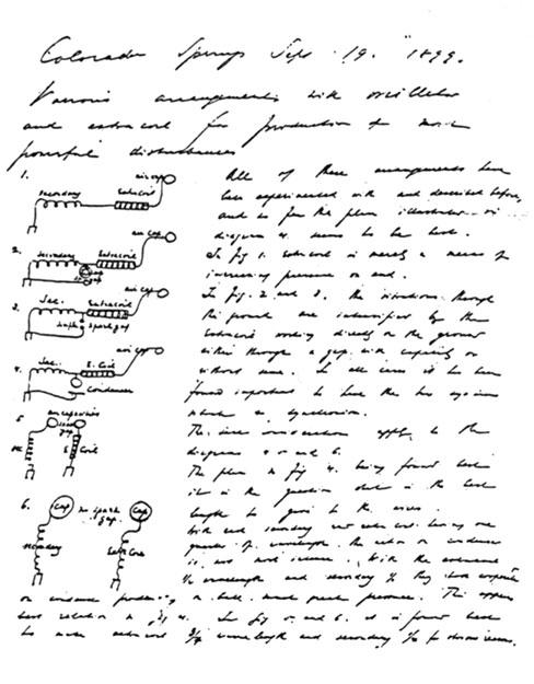
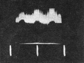
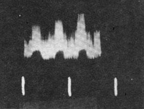
The wiring diagram of the preceding illustrations and photographs is found in Tesla’s laboratory notes (7) and shown in Figure 7. Of this group of circuits, it is circuit 2 that matches the circuit of the model Power Wave generator. The Power Wave generator creates the wave shapes shown in Photos 3,4, and 5 by adjusting the pendulum and surround plate.
Power Wave Forms
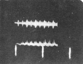
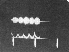
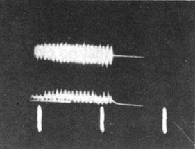
My wave shapes were of the correct frequency range for the low frequency of the Power Wave, but they were not sine waves, which are required for Tesla’s experiment. The oscilloscope photographs were taken .2 seconds per division scan and .1 volts per division amplitude.I found that by rectifying the modulated wave shapes, I would be closer to the sine wave. Looking back at Tesla’s work and the work of others at the turn of the century, I found that the point-plane spark gap rectification was generally understood but not formally published until Dudel documented it in 1908. (4) There was somewhat of a point-plane spark gap arrangement between the top of the third coil and the bottom of Tesla’s antenna as shown in Photo 2. When this point-plane gap arrangement was tried on my model generator, it showed moderate rectification but no sine wave.
Something was still missing to create the Power Wave. Turning to other experiments of the Colorado Springs Notes, I found the following entry of June 26, 1899 (Figure 8). (7)
These experiments demonstrated Tesla’s understanding of how to separate the mass of heavy and light gas molecules such as mercury and hydrogen by means of high voltage potential. On July 5, 1899, Tesla’s entry in the lab notes refers to convenient hydrogen production using a hot wire along with certain hydrocarbons of ethanol. (7)
Figure 8 - Separating Gas Mixtures.
Colorado Springs
June 26, 1899In following up an old idea of separating gaseous mixtures by the application to them of an excessively high electromotive force, the following apparatus is to be adopted with a new oscillator.

Note: in this apparatus it will be preferable to use a form of oscillator with mercury break supplied from a source of direct current, so that the force on T will be mostly uni-directional. Any other generator developing the necessary e.m.f. should, however, accomplish the same result.
Three tubes t1t2t3 (assuming only three will be needed) are slipped one into the other, being held apart by insulating plugs a b c. In these plugs are fastened outlet tubes A B C to lead the several separated gases away to reservoirs into which they may be compressed. It is therefore to be understood that there is the desired degree of suction on the outlet pipes, or else the mixture is forced under desired pressure through an insulating plug P fastened into the largest tube t1. The particles of the gas coming in contact with the active terminal are thrown away with great force and are projected at different distances according to their size and weight, hydrogen farther than most others. The latter element, if it be present, will therefore pass through tube, A, that is mostly, the heavier and larger molecules through the other tubes. By repassing the gases drawn off through the apparatus again, any degree of purification or separation is obtained.
To understand Tesla’s discovery, I find it relevant to look at the discoveries going on at the same time. In 1884 Tesla arrived in New York and started working for Thomas Edison. (2) Only a year earlier Edison had been granted a patent for an electrical indicator (Figure 9), called the Edison Effect. (5)
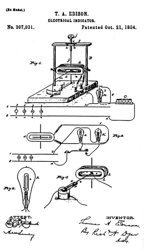
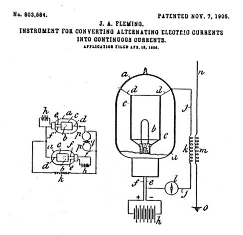
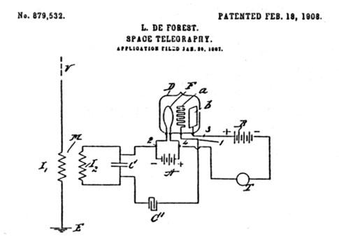
The Edison Effect showed that electrons would pass from a hot filament to a cold plate whenever the plate was at a positive potential with respect to the filament, but that no electrons would pass in either direction if the plate was more negative than the filament. (5)Notice also how soon in history the other inventions were to follow: the Fleming valve or Audion (1905); a vacuum tube rectifier (1905) (Figure 10); and De Forest’s modulating triode (1908) (Figure 11). Also during this period J.J. Thomson deflected electrons in a vacuum with a magnetic and electrostatic field to successfully quantify electron mass.
Tesla’s recollection of this Edison Effect, combined with his own heavy molecule/light molecule experiments with hydrogen, mercury vapor or plasma, led to the procedure he used in his Colorado Springs experiment. Tesla, reflecting back to this time concerning his #685,958 patent of 1901, (8) said:
It is well known that certain radiations - such as those of ultraviolet light, cathodic, Roentgen rays, or the like, possess the property of charging and discharging conductors of electricity; the discharge being particularly noticeable when the conductor upon which the rays impinge is negatively electrified. [Reflecting on the Edison Effect?] These radiations are generally considered to be ether vibrations of extremely small wave lengths, and in explanation of the phenomena noted, it has been assumed by some authorities that they ionize or render conducting the atmosphere through which they are propagated. My own experiments and observation, however, lead me to conclusions more in accord with the theory heretofore advanced by me that sources of such radiant energy give off with great velocity minute particles of matter which are strongly electrified, and therefore capable of charging an electrical conductor either by carrying off bodily its charge or otherwise.
Tesla undoubtedly tried mercury ions in his June 26, 1899 device (Figure 8). If so, he must have noticed a strong charge separation when using AC current, not DC, and instructed everyone to keep it confidential. This is reflected in Scherff’s letter to Tesla (8), Figure 12.
Figure 12 - Scherff's Letter to Tesla.
New York, Sep. 26th, 1899
46 & 48 E. Houston StreetNikola Tesla, Esq.,
Colorado Springs, Colo.Dear Mr. Tesla:
The work of the shop is on the castings, pulley and different brass parts of the fourth break.
Mr. Loewenstein has returned to-day and work on the coherers, about which he had instructions, has also been begun.
Mr. Uhlman says some further improvement has been made in the pump, the same works now very well and gives a very steady light, and duplicates of it will be made for the other breaks. I have not forgotten your recent censure for writing so often on this subject and wish to beg your pardon for touching upon it again - for the last time, I hope.
The mail to-day consisted of the inclosed bill and two applications for positions, one from Mr. Lee De Forest and one from Mr. Barnum C. McCusker. I have informed both applicants of your absence.
Respectfully,
Geo. Scherff
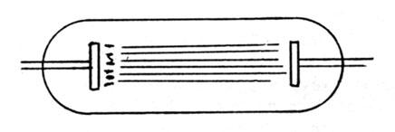
Many hypothetical scenarios come to mind, but one thing is clear: Tesla was trying mercury and hydrogen plasmas that generate ultraviolet light. Ultraviolet rays always accompany mercury plasma in a vacuum. These experiments would lead to a mercury rectifier. Impinging Roentgen rays would require a vacuum tube of the type shown in Figure 13. (4)
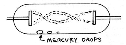
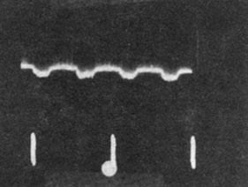
Impinging ultraviolet waves would require a vacuum tube of the design shown in Figure 14. I now constructed a mercury tube and installed it inside the iron antenna of the Power Wave generator model shown in Figure 5. The result was the sought-after sinusoidal Power Wave. A nearby broadband antenna attached to a Phillips memory scope created Photos 6 and 7 (using two different Tesla Coils). Photo 8 was taken using a Hewlett-Packard scope and a Hewlett-Packard camera, with shutter open during one trace (.2 sec/div and .1 V/div). Each of the photos resembles what previously mentioned would best meet the requirements of these graphs. (Figure 15)
Earth Resonance Frequency + Practical Size Receiver = Power Wave (combined frequency)
A Mercury Rectifier
Now let us speculate on evidence indicating that Tesla may have had a mercury rectifier inside his antenna.
At high voltage and power the mercury arc or plasma would generate much heat. Maybe that is why Tesla chose heavy iron pipe (iron being a relatively poor conductor compared to copper or tin, and much heavier). At high temperatures, however, iron retains its strength, unlike copper or tin. Perhaps Tesla reasoned that iron would survive a high temperature mercury plasma inside the antenna without bending.
The fact that Tesla chose to thread the bottom section of the pipe, but used rivets on all other joints is also curious. Threaded fittings are stronger and more weather-tight than rivets. Stranger still is the record of him having the joints wrapped with sheet latex, then wrapped with cord, and finally painted with latex. Figure 16 shows Tesla’s specifications for the antenna. This man, who patented finely-polished and engineered reciprocal piston devices and bladeless turbines, was putting “bandages” at the joints of the antenna of his most prized effort. The latex must have had some other purpose.
Figure 16 - Antenna Specifications.
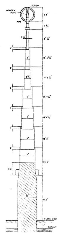
Colorado Springs
Oct. 17, 1899Structure for capacity of extra coil, for investigation of earth vibrations chiefly.
This structure was erected on a pole 10" x 10" square, tapering on top. Dry fir was used because of toughness and also resinous quality. Pipes of steel of diameters 7", 6", 5", 4", 3 1/2", 3" and 2 1/2" were used. They were shoved one into the other and riveted, four rivets were used on each joint, the lap being 2'.
The lengths of pipes were as follows:
7" diam. 23' 4" 6" " 18' 2" 5" " 18' 4 1/2" 4" " 15' 7 1/4" 3 1/2" " 19' 3 1/4" 3" " 18' 4 3/4" 2 1/2" " 8' 1/4" Nipples on top 7 3/4" Total length of pipes 121' 9 3/4" Firwood pole 19' 3" Total from floor 141' 3/4" to ground 1' Total height from ground to bottom of ball 142' 3/4" On the top was supported a ball of 30" diam. hollow wood covered with tin foil very smoothly and the joints indented so as to have no conducting points sticking out. The joints of the pipes, heads of the rivets, etc. were all covered first with sheet rubber pure then with tape, the latter being finally fastened with strong cord. The ball was shellaced several times and finall covered with weatherproof rubber paint. The pole all along was also painted with the same paint. On the lowest end of the 7" pipe a cap was screwed clearing the wood so as to make it more difficult for the streamers to get to the ground along the pole.
* To prevent lateral play 8 champagne bottles set in beams were used.

One exciting thought is that if hydrogen were introduced through a hole to the inside of the antenna at the bottom, it would displace the air within, being lighter than air. Mercury could be introduced through the same hole. After electrodes were installed, the hole could be plugged up with a device that would monitor to what extent the inside of the antenna was being evacuated. (Figure 17)
A request that such a device be built can be found in Tesla’s letter to Scherff shown in Figure 18. Notice also in this letter Tesla’s additional request that the secret be strictly adhered to. The vacuum monitor is drawn at the bottom of the antenna (Figure 17). When a discharge passed through this tube, an experienced eye could not only tell the degree of vacuum, by color and pattern, but also the nature of residual gases. (4) Tesla, more clever than most, partitioned half the tube to have that half pre-evacuated by a known amount, which served as a standard for comparison.
Tesla could now strike a powerful arc, perhaps using the Westinghouse transformer in his lab, or the capacitor bank, or both. If necessary he could tap into the top of the secondary coil for a couple million volts. Once struck, the mercury arc inside the antenna would cause the temperature of the hydrogen to rise. The latex joints would not contain the hydrogen since the gas can go through latex in the same fashion it goes through the walls of a balloon. Mercury is a much larger molecule and would be trapped inside. Outside air could not get in since it is also a large molecule and cannot go through a latex seal. When the antenna cooled, it would contain a vacuum. The sequence could be repeated as necessary until the vacuum indicator glowed in a color and pattern that indicated the proper vacuum was within.If the antenna caught fire from the hydrogen and electricity, then Tesla would probably order smaller tubes to be made of glass and inserted inside the antenna in a series arrangement, which would distribute the voltage and power requirements of the whole system safely over each bottle so that each would experience only a small fraction, and the bottoms of the tubes/bottles would not break. (6)
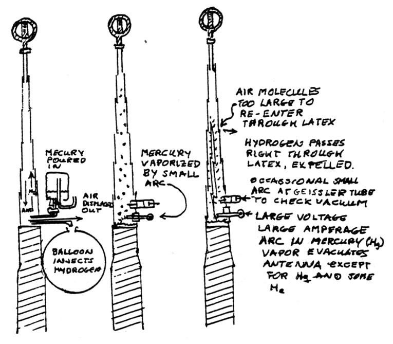
Figure 18 - Telegram from Tesla to Scherff.
Colorado Springs, Oct. 14, 1899
Dear Mr. Scherff,
I have expressed to-day some photos illustrating a few of my experiments here. One of them, as you will see is for my friend Mrs. Ledenbury (?) on 38th St. and Madison Ave. All the others for my friend, J. J. A. When you get these, open the box carefully and lover over the photographs, be sure they are perfectly clean, then pack up nicely and deliver them yourself at the houses.
I want you to show them to Mr. Uhlman but not to others. Of course they must not go further. I am sorry to say the clockwork did not pan out right, besides, it is too big for a box I designed here. Mr. Uhlman should try to make the stop in the manner indicated by me, and all as small as possible. There is a finer clockwork to be had. He can make the lever bear upon a disc of larger diameter, or stop the clockwork by a magnet in the manner of escapement. This ought not to be difficult.
As to the point receiver, the chief is to have the points meeting in a very narrow tube and have the exhaustion 75 millimeters pressure, or perhaps 100 mm. The tube should be as in sketch.
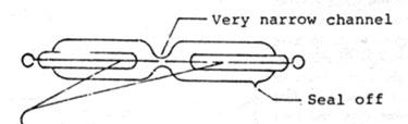
Platinum wire sealed in glass all together, only very fine sharpened points (polished) exposed. The points as close together as possible, perhaps it would be best to make them actually touch, being very fine, I can burn the points off with the current off so as to leave microscopical space between. Pressure 75-100 mm. To get the pressure right the glass blower should connect a tube to a gauge and seal off when the right pressure is obtained. I would like two tubes made like this:
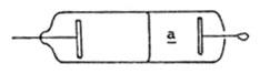
A tube with 2 compartments, at "a" minute hole drilled through by a jeweller, a plate of aluminum and wire in each compartment. Tube about 1/4"-3/8" diameter. 1-2" long.
Sincerely,
N. Tesla


The other tube ordered in the October 14, 1899 letter must have been the world’s first oscilloscope (Figure 19). The narrow part of the tube was needed to get the high power objective of a microscope (a short focal length) close enough to the electrodes to see which one glowed (polarity) when an antenna was attached to one end of the tube and to a ground wire at the other end. The frequency or scan of this scope was a rotating mirror or a spinning disk with holes (shutter strobe-chopper) attached to a clockwork for frequency calculations. When the shutter speed was just right, the wave shape could be observed on one electrode, which depended on the wave being plus or minus.
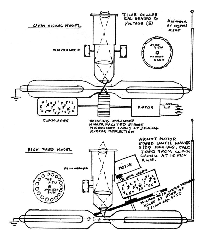
The selection of optical magnification would be the amplitude selection or vertical gain. The clockwork and the stopwatch would be the horizontal scan rate or frequency. Tesla must have wanted to be very secretive not to have patented this wonderful test instrument and the mercury rectifier.
With Tesla’s mercury rectifier, oscilloscope, and colorimetric chamber Geissler tube, it would have been possible for him to monitor the evacuation of the antenna and to see that the necessary sine wave was produced for propagation around the earth. His stressing the secrecy of these items leads me to believe that each of his discoveries worked and that he knew the implications of his discoveries. Today, using modern oscilloscopes and Tesla’s notes, I have recreated the production of the 8 Hz Power Wave that Tesla produced in 1899. Superimposed on this wave is a 60 kHz wave, carried by the 8 Hz wave, which is easily captured by small devices for power or transportation.
Final Note: Tuning the Antenna
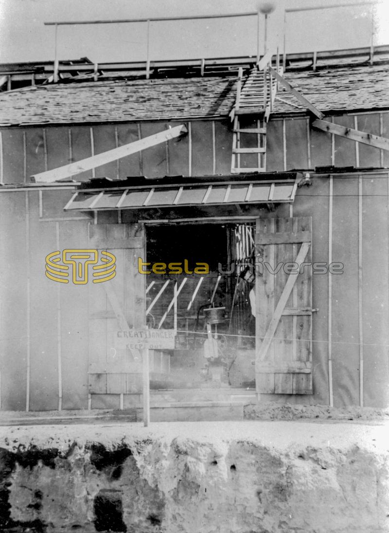
From Photo 9 one can see a very long trench was dug in front of the entrance to Tesla’s lab. The patent Tesla applied for on June 15, 1900 (Figure 20) indicates that he had the option of a very good ground or a Roger’s underground radio antenna. This additional 1899 antenna afforded Tesla a wide variety of parameters for tuning the entire system. If you look again at Photo 1, at the area marked “trench,” it shows that the length of the trench was many times the length of Tesla’s lab. The trench size indicates that it could have contained a buried antenna of the type shown in the patent below.
The tuning or coupling of the Tesla Power Wave Generator of 1899 must have been accomplished with the buried antenna working with the vertical antenna above the lab. The subject of his antenna tuning is too extensive to be included in this paper. It is mentioned here so that the Power Wave ideas presented in this paper shall not be discredited with an over-simplified consideration of the length of the vertical antenna above Tesla’s 1899 lab. (It was, after all, a very cold freezing December in Colorado in which the final test was completed in 1899. Maybe Colorado was chosen for its cold Decembers. The beginnings of cryogenics! Colorado Springs is also one mile high on top of red iron oxide soil and minerals, which at 8 Hz is part of the antenna length! )
References
- Chamot and Mason. Chemical Microscopy. New York: John Wiley and Sons, Inc., 1930, p 427.
- Cheney, M. Tesla: Man Out of Time. Englewood Cliffs, New Jersey: Prentice Hall, Inc., 1981, p 27.
- “Mode Theory and the Propagation of ELF Radio Waves,” Journal of Research of the National Bureau of Standards, D. Radio Propagation, Vol. 64D, No. 4, July-August 1960, pp 387-404.
- Kaye, G.W.C., D.Sc., O.B.E. X Rays. London: Longmans Green and Co., 1923.
- Kloeffler, Royce G., S.M. Basic Electronics. New York: John Wiley and Sons, Inc., 1949.
- Ratzlaff, John T., and Fred A. Jost. Dr. Nikola Tesla. Millbrae, California: Tesla Book Company, 1979.
- Tesla, Nikola. Colorado Springs Notes, 1899-1900. Prepared for publication by the Nikola Tesla Museum. Beograd, Yugoslavia: Nolit, 1978.
- Tesla, Nikola. Complete Patents. Millbrae, California: Tesla Book Company, 1983, p 432.
Ron Kovac received his Bachelor of Science degree in chemistry from the University of Colorado in 1965. He continued graduate studies in analytical chemistry at Colorado University and later earned a certificate of Business Management Development from Colorado University.
Early in his career, Kovac worked as an Associate Geophysical Research Scientist at the National Center for Atmospheric Research (NCAR).He later worked in the areas of retail electronics and computer design. He is currently president of Mountain States Mining & Smelting, and active in scientific equipment sales. He may be contacted at: 1165 Hancock, Boulder, CO 80303.