Nikola Tesla Patents
Nikola Tesla British Patent 185,446 - Method of and Apparatus for Aerial Transportation
PATENT SPECIFICATION
185,446
Application Date: Apr. 4,1921. No. 9961/21.
Complete Left: Sept. 5, 1921.
Complete Accepted: Sept. 4, 1922.
PROVISIONAL SPECIFICATION.
Method of and Apparatus for Aerial Transportation
I, Nikola Tesla, Mechanical and Electrical Engineer, citizen of the United States of America, of 8, West 40 Street, New York City, U.S.A., do hereby declare the nature of this invention to be as follows:-
The utility of the aeroplane as a means of transport is materially lessened and its commercial introduction greatly hampered owing to the inherent inability of the mechanism to readily rise and alight, which is an unavoidable consequence of the fact that the required lifting force can only be produced by a more or less rapid translatory movement of the planes or foils. In actual experience the minimum speed for ascension and landing is a considerable fraction of that in full flight and the principles of design do not admit of a very great advance in this respect without sacrifice of some desirable features. For this reason planes of very large area, high lift wing-sections, deflectors of the slipstream of the propeller, or analogous means, which might be helpful in these operations, do not afford the remedy sought. This indispensable high velocity, imperilling life and property, makes it necessary to equip the machine with special appliances and provide suitable facilities at the terminals of the route, all of which entail numerous drawbacks and difficulties of a serious nature. So imperative has it become to discover some way of doing away with these limitations of the aeroplane that the consensus of expert opinion characterizes the problem as one of the most pressing and important and its practical solution is eagerly awaited by those engaged in the development of the art, as well as the general public.
Many attempts have been made to this end, mostly based on the use of independent devices for the express purpose of facilitating and insuring the start and finish of the aerial journey, but the operativeness of the arrangements proposed is not conclusively demonstrated and, besides, they are objectionable, constructively or otherwise, to such an extent that builders of commercial apparatus have so far not considered them of sufficient value to depart from present practice.
More recently, professional attention has been turned to the helicopter which is devoid of planes as distinct organs of support and, presumably, enables both vertical and horizontal propulsion to be satisfactorily accomplished through the instrumentality of the propeller alone. However, although this idea is quite old and not a few experts have endeavored to carry it out in various ways, no success has as yet been achieved. Evidently, this is due to the inadequacy of the engines employed and, perhaps, also to certain heretofore unsuspected characteristics of the device and fallacies in the accepted theory of its operation, an elucidation of which is deemed necessary for the clear understanding of the subject.
The prospects of a flying machine of this kind appear at first attractive, primarily because it makes possible the carrying of great loads with a relatively small expenditure of energy. This follows directly from the fundamental laws of fluid propulsion, laid down by W. T. M. Rankine more than fifty years ago, in conformity with which the thrust is equal to the integral sum of the products of the masses and velocities of the projected air particles; symbolically expressed, T=Σ(mv).
On the other hand, the kinetic energy of the air set in motion is E=Σ(½mv2)
From these equations it is evident that a great thrust can be obtained with a comparatively small amount of power simply by increasing the aggregate mass of the particles and reducing their velocities. Taking a special case for illustration, if the thrust under given conditions be ten pounds per horsepower, then a hundredfold increase of the mass of air, accompanied by a reduction of its effective velocity to one-tenth, would produce a force of one hundred pounds per horsepower. But the seemingly great gain thus secured is of little significance in aviation, for the reason that a high speed of travel is generally an essential requirement which can not be fulfilled except by propelling the air at high velocity, and that obviously implies a relatively small thrust.
Another quality commonly attributed to the helicopter is great stability, this being, apparently, a logical inference judging from the location of the centers of gravity and pressure. It will be found, though, that contrary to this prevailing opinion the device, while moving in any direction other than up or down, is in an equilibrium easily disturbed and has, moreover, a pronounced tendency to oscillate. It is true, of course, that when the axis of the propeller is vertical and the ambient air quiescent the machine is stable to a degree, but if it is tilted even slightly, or if the medium becomes agitated, such is no longer the case.
In explanation of this and other peculiarities, assume the helicopter poised in still air at a certain height, the axial thrust T just equalling the weight, and let the axis of the propeller be inclined to form an angle a with the horizontal. The change to the new position will have a twofold effect: the vertical thrust will be diminished to Tv= T sin α, and at the same time there will be produced a horizontal thrust Th = T cos α.
Under the action of the unbalanced force of gravity the machine will now fall along a curve to a level below and if the inclination of the propeller as well as its speed of rotation remain unaltered during the descent, the forces T, Tv and Th will continuously increase in proportion to the density of the air until the vertical component Tv of the axial thrust T becomes equal to the gravitational attraction. The extent of the drop will be governed by the inclination of the propeller axis and for a given angle it will be, theoretically, the same no matter at what altitude the events take place. To get an idea of its magnitude suppose the elevations of the upper and low strata measured from sea level be h1 and h2, respectively, d1 and d2 the corresponding air densities and H = 26,700 feet the height of the “uniform atmosphere”, then as a consequence of Boyle’s law the relation will exist
$! {h_{1} - h_{2} = H \log_{e} {d_{2} \over d_{1}}} $!
It is evident that $! {{T \over T_{v}} = {T \over T} \sin a = {1 \over \sin a} = {d_{2} \over d_{1}}} $! in order that the vertical component of the axial thrust in the lower stratum should just equal the weight. Hence
$! {h_{1} - h_{2} = H \log_{e} {1 \over \sin a}} $!.
Taking, in a special case, the angle a = 60°, $! {1 \over \sin a} $! = $! {1 \over 0.866} $! = 1.1547 and h1 - h2 = 26,700 x loge 1.1547 = 3840 feet.
In reality, the drop will be much greater for the machine, upon reaching the lower layer with a high velocity relative to the medium will be urged further along the path and the kinetic energy, in the vertical sense, possessed by the moving mass must be annihilated before the fall is arrested in a still denser air stratum. At this point the upward thrust will be far in excess of the opposed pull of the weight and the apparatus will rise with first increasing and then diminishing speed to nearly the original height. From there it will again fall and so on, these operations being repeated during the forward flight, the excursions gradually diminishing in magnitude. After a lapse of time, determined by numerous influences, the oscillations should cease altogether and the path described become rectilinear. But this is next to impossible as can be readily shown by pointing out another curious feature of the helicopter.
In the foregoing the axis of the propeller was supposed to move always parallel to itself, which result might be accomplished by the use of an adjustable aileron. In this connection it may be pointed out that such a device will not act in the manner of a rudder, coming into full play at intervals only and performing its functions economically, but will steadily absorb energy, thus occasioning a considerable waste of motive power and adding another to the many disadvantages of the helicopter.
Let now the machine be possessed of a certain degree of freedom, as will be the case normally, and observe in the first place that the blades of the propeller themselves constitute planes developing a reaction thrust, the pressure on the lower leading blade being greater than that exerted on the higher one owing to the compression of the air by the body of the machine and increased density in that region. This thrust, tending to diminish the angle α, will obviously vary during one revolution, being maximum in a position when the line of symmetry of the two propeller blades and that of flight are in a vertical plane and minimum at right angles to it; nevertheless, when the horizontal speed is great it may be considerable and sufficient to quickly overcome the inertia and gyroscopic resistances. Moreover, this disturbing effect partakes of the regenerative quality, the force increasing as the angle α diminishes up to a maximum for α = 45°. As the axis is tilted more and more, the vertical sustaining effort of the propeller will correspondingly diminish and the machine will fall with a rapidly increasing velocity, finally exceeding the horizontal when the reaction of the blades will be directed upward so as to increase the angle a and thereby cause the machine to soar higher. Thus periodic oscillations, accompanied by ascents and descents, will be set up which may well be magnified to an extent such as to bring about a complete overturn and plunge to earth.
It is held by some experts that the helicopter, because of its smaller body resistance, would be capable of a higher speed than the aeroplane. But this is an erroneous conclusion, contrary to the laws of propulsion. It must be borne in mind that in the former type, the motive power being the same, a greater mass of air must be set in motion with a velocity smaller than in the latter, consequently it must be inferior in speed. But even if the air were propelled in the direction of the axis of the screw with the same speed V in both of them, while the aeroplane can approximate the same, the helicopter could never exceed the horizontal component V cos α which, under the theoretically most economical conditions of operation, would only be 0.7V.
Another very serious defect of this kind of flying machine, from the practical point of view, is found in the inability of supporting itself in the air in case of failure of the motor, the projected area of the propeller blades being inadequate, for reducing the speed of the fall sufficiently to avoid disaster, and this is a fatal impediment to its commercial use.
From the preceding facts, which are ignored in the technical publications on the subject, it will be clear that the successful solution of the problem is in a different direction.
My invention meets the present necessity in a simple manner without radical departures in construction and sacrifice of valuable features, incidentally securing advantages which should prove very beneficial in the further development of the art. Broadly expressed, it consists in a novel method of transporting bodies through the air in which the machine is raised and lowered solely by the propeller and sustained in its flight by planes. The chief innovations in the mechanism are a prime mover of the kind described in my British Patent No. 24,001 of 1910, a specially designed propeller and arrangements whereby the machine is automatically, or through wilful control, transformed from the helicopter into an aeroplane and vice versa.
In the preferred form of design the structure is composed of two planes or foils rigidly joined, their length and distance apart being such as to form a square for the sake of smallness and compactness. With the same object the tail is omitted or, if used, it is retractable. The turbine and other parts of the motive apparatus are placed as in an aeroplane and also the usual controls are provided. At rest the planes are vertical or nearly so and likewise the propeller which is relatively large and built for great strength in order to support safely the entire weight. The seat of the aviator and passengers is suspended on trunnions on which it can turn through an angle of about 90°, springs and cushions being employed to insure and limit its motion through this angle. Hand- and foot-controlled devices are placed so as to be within easy reach of the driver in any position.
At the start, power being turned on, the machine rises vertically in the air to the desired height when it is gradually tilted and becomes an aeroplane, the foils taking up the load as the speed in the horizontal direction increases. In descending, the forward speed is reduced and the machine righted again, becoming a helicopter with the propeller supporting all the load. The turbine referred to is a motor of exceptional lightness and activity and lends itself to this kind of use for which ordinary aviation motors are unsuited. It is capable of carrying a great overload and running without danger at excessive speed so that in the starting and landing operations the necessary power can be developed, even though less efficiently than under normal conditions. However, should the propelling mechanism fail, landing can still be effected without much risk in the usual manner. Such a helicopter-plane constructed as indicated and operated in the manner described, unites the advantages of both types and seems to meet best the requirements of a small, compact, exceedingly speedy and yet very safe machine for commercial use.
Dated this 31st day of March, 1921.
Nikola Tesla.
COMPLETE SPECIFICATION.
Method of and Apparatus for Aerial Transportation.
I, Nikola Tesla, Electrical and Mechanical Engineer, citizen of the United States of America, of 8, West 40th Street, New York, N.Y., U.S.A., do hereby declare the nature of this invention and in what manner the same is to be performed, to be particularly described and ascertained in and by the following statement:-
This invention relates to aerial machines of the kind in which the machine is adapted to be raised and lowered in the manner of a helicopter with the chords of the planes and the axis of the propelling means vertical and in which the planes and propelling means are adapted to be turned through a right angle in the air so that the chords of the planes and the axis of the propelling means are more or less horizontal and the machine can be flown as an aeroplane.
The utility of the aeroplane as a means of transport is materially lessened and its commercial introduction greatly hampered owing to the inherent inability of the mechanism to readily rise and alight, which is an unavoidable consequence of the fact that the required lifting force can only be produced by a more or less rapid translatory movement of the planes or foils. In actual experience the minimum speed for ascension and landing is a considerable fraction of that in full flight, and the principles of design do not admit of a very great advance in this respect without sacrifice of some desirable feature.
More recently professional attention has been turned to the helicopter, which is devoid of planes as distinct organs of support, and, presumably, enables both vertical and horizontal propulsion to be satisfactorily accomplished through the instrumentality of the propeller alone. However, although the idea is quite old and not a few experts have endeavored to carry it out in various ways, no practical success has yet been achieved.
A very serious defect of this kind of flying machine, from the practical point of view, is found in its inability of supporting itself in the air in case of failure of the motor, the projected area of the propeller blades being inadequate for reducing the speed of the fall sufficiently to avoid disaster, and this is an almost fatal impediment to its commercial use.
The type of machine to which this invention relates enables many of these disadvantages to be avoided but in order to obtain practical success I have found that provision must be made for the very different burdens which investigation shows fall upon the engine when the machine is being raised vertically and when it is being propelled horizontally and that to accomplish this an engine must be employed which is capable of standing a considerable over-load during the period of vertical ascent and of rotating at greatly increased speed during this time compared with the speed to be normally used during horizontal flight.
One of the features of this invention is the construction of an aeroplane of the above-named type actuated by an engine adapted to run at such over-load and for this purpose I use a prime-mover of the kind described in my British Patent No. 24,001 of 1910.
Another feature is that the machine is so constructed that it can start or descend either vertically as an helicopter or at an angle as an aeroplane and for this purpose two landing bases approximately at right angles to one another are provided.
Other subsidiary features of the invention are set out in the description following.
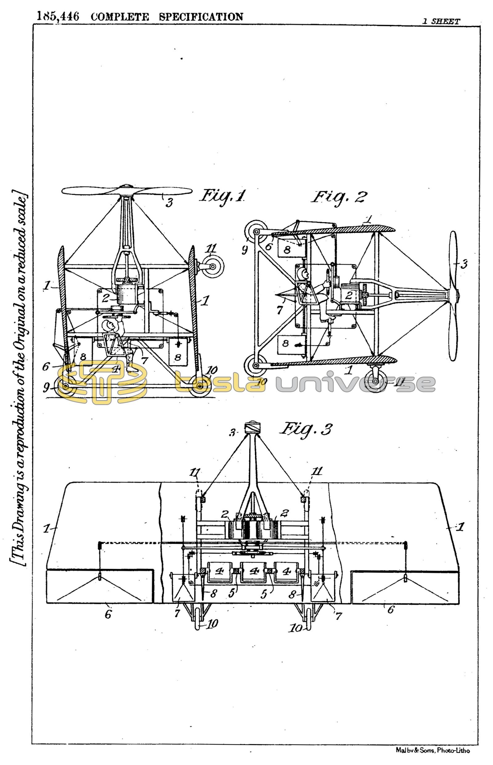
Full knowledge of these improvements will be readily gained by reference to the accompanying drawings in which Fig. 1 illustrates the machine in the starting or landing position and Fig. 2, in horizontal flight. Fig. 3 is a plan view of the same with the upper plane partly broken away.
The structure is composed of two planes or foils 1, 1, rigidly joined, the chord and gap of which may be nearly equal. The tail is omitted or, if used, it should be retractable. The motors 2, 2, in this case turbines of the kind described in my patent before referred to, and other parts of the motive apparatus are placed with due regard to the centres of gravity and pressure and the usual controlling means are provided. In addition to these any of the known stabilizing devices may be embodied in the machine. At rest the planes are vertical, or nearly so, and likewise the shaft driving the propeller 3, which is constructed of a strength, size and pitch that will enable it to raise the entire weight with the motor running at an even greater rate than when propelling the machine horizontally. Power is transmitted to the shaft from the turbines through suitable gears. The seats 4, 4, 4, for the operator and passengers are suspended on trunnions 5, 5 on which they may turn through an angle of about 90°, springs and cushions (not shown) being employed to insure and limit their motion through this angle. The usual devices for lateral and directional control, 6, 6, 7, 7, and 8, 8 are provided with mechanical connections enabling the operator to actuate the devices by hand or foot from his seat in any position. At the start, sufficient power being turned on by suitable means, also within his reach, the machine rises vertically in the air to the desired height when it is gradually tilted by manipulating the elevator devices and proceeds like on aeroplane, the load being transferred from the propeller to the foils as the angle of inclination diminishes and the speed in horizontal direction increases. In descending the forward speed may be reduced and the machine righted again, acting as a helicopter with the propeller supporting all the load. The type of turbine which, as stated above, I prefer is a motor of great lightness and activity and lends itself exceptionally to this kind of work for which ordinary aviation motors are unsuited. It is capable of carrying a great overload and running without danger at excessive speed so that during the starting and landing operations the necessary power can be developed by the motors even though less efficiently than under their normal working conditions. Special means of control may be provided, if necessary, for increasing the power supply in these operations. Owing to its extreme simplicity the motive apparatus is very reliable in operation. Ascent and descent can be effected either with the planes vertical or in the manner of aeroplanes of the usual type. For this purpose, in addition to wheels 9, 9 and 10, 10, wheels 11, 11 are employed, the latter being mounted on the forward end under the lower plane so that when the machine rests on level ground the propeller shaft will have the desired inclination which is deemed best for rising in the manner of an aeroplane. Such a helicopter-plane constructed and operated as described, unites the advantages of both types and seems to meet best the requirements of a small, compact, exceedingly speedy and yet very safe machine for commercial use.
Having now particularly described and ascertained the nature of my said invention, and in what manner the same is to be performed, I declare that what I claim is:-
- A flying machine capable of vertical movement under the influence of its propeller or propellers and also of movement in the manner of an aeroplane actuated by a motor or motors so constructed that it or they are adapted to rotate its propeller or propellers at a speed greatly exceeding normal when rising or descending vertically while such speed can be reduced to the normal when it is flying horizontally and supported by its planes.
- Flying machine as described and claimed in Claim 1 of which the motor or motors are of the type described in British Specification No. 24,001 of 1910.
- Flying machine as described and claimed in the preceding claims actuated by a single propeller which when it is ascending vertically is above the centre of gravity of the machine.
- A flying machine so constructed that it can start and descend either straight up and down like a helicopter or at an angle like an aeroplane and can be tilted as a whole in the air from its vertical to its horizontal position and vice versa, substantially as described.
- Flying machine as described and claimed in Claim 4 provided with two wheel bases substantially at right angles.
- Flying machine as described and claimed in the preceding claim in which one or more wheels are common to the two bases.
- Flying machine constructed substantially as described and shown in the drawings.
Dated this 25th day of August, 1922.
Nikola Tesla,
By James R. Hatmaker,
His Attorney.