Nikola Tesla Patents
Nikola Tesla British Patent 186,084 - Improved Process of and Apparatus for Deriving Motive Power from Steam
PATENT SPECIFICATION
186,084
Application Date: Mar. 24, 1921. No. 9100/21.
Complete Left: Sept. 2, 1921.
Complete Accepted: Sept. 25, 1922.
PROVISIONAL SPECIFICATION.
Improved Process of and Apparatus for Deriving Motive Power from Steam
I, Nikola Tesla, Mechanical and Electrical Engineer, Citizen of the United States of America, of 8, West 40 Street, New York City, U.S.A., do hereby declare the nature of this invention to be as follows:
This improvement provides a very simple means for increasing the economy of steam turbines and is chiefly intended to be used in the operation of small units but may also be applied, with more or less success, to machines of considerable capacity, the saving effect depending largely on the conditions existing in the steam-plants where it is introduced. The economic gain will be especially pronounced in factories and industrial establishments in which the steam pipes are long and serious loss is incurred through condensation and otherwise. The apparatus for carrying out the process is capable of slight modifications and can be employed in conjunction with different types of turbines, but is particularly suited to that described in my British Patent No. 24,001 of 1910, in which propulsion is effected by the adhesive and viscous action of the motive fluid. Irrespective of constructive features the general arrangement will be as follows:
The steam from the boiler is led through a superheater to the turbine nozzle and the high velocity jet projected from it against the rotor creates a suction in the adjacent space which is connected to the superheater pipes or coils, thus causing a strong air current to pass through the same. The air first enters a chamber to which gas or other fuel is supplied and the products of combustion are aspired through the coils into the turbine, superheating the steam to the desired degree, also increasing the temperature of the stream through the turbine rotor and, incidentally, imparting to it some of their kinetic energy. All of these actions co-operate in raising the efficiency of the machine with the result of bringing about an important reduction of operative expense.
To improve the performance of the apparatus I employ two concentric nozzles, steam being admitted to the turbine through one and the products of combustion through the other. Furthermore, in order to turn to good use the waste heat of the exhaust I attach to the latter an economiser for preheating the feedwater and fuel, thereby effecting additional saving.
This invention dispenses with the compressor ordinarily required in connection with a gas turbine and will be found valuable on account of its extreme simplicity, low cost of installment and facilities it affords.
Dated this 24th day of March, 1921.
Nikola Tesla.
COMPLETE SPECIFICATION.
Improved Process of and Apparatus for Deriving Motive Power from Steam.
I, Nikola Tesla, Electrical and Mechanical Engineer, citizen of the United States of America, of 8, West 40th Street, New York, N.Y., U.S.A., do hereby declare the nature of this invention and in what manner the same is to be performed, to be particularly described and ascertained in and by the following statement:-
This improvement provides a very simple means for increasing the economy of steam turbines and is chiefly intended to be used in the operation of small units but may also be applied, with more or less success, to machines of considerable capacity, the saving effect depending hugely on the conditions existing in the steam-plants where it is introduced. The economic gain will be especially pronounced in factories and industrial establishments in which the steam pipes are long and serious loss is incurred through condensation and otherwise. The apparatus for carrying out the process is capable of slight modifications and can be employed in conjunction with different types of turbines, but is particularly suited to that described in my British Patent No. 24,001 of 1910, in which propulsion is effected by the adhesive and viscous action of the motive fluid. Irrespective of constructive features the operation will be generally as follows:
The steam from the boiler is led to the nozzle through a superheater, which should be placed as near as possible to the turbine, and the high velocity jet, projected from it against the rotor, creates a suction in the adjacent space which is connected to the superheater pipes or coils, thus causing a strong air current to pass through the same. The air first enters a combustion chamber to which gas or other fuel is supplied and the products are aspirated through the coils into the turbine, superheating the steam to the desired degree, also increasing the temperature of the stream through the turbine rotor and, incidentally, imparting to it some of their kinetic energy. All of these actions co-operate in raising the efficiency of the machine with the result of bringing about an important reduction of operative expense.
To improve the performance of the apparatus, I preferably employ two concentric non-convergent nozzles, steam being admitted to the turbine through one and the products of combustion through the other. Furthermore, in order to turn to good use the waste heat of the exhaust I may attach to the latter an economiser for preheating the feed-water and fuel, thereby effecting additional saving.
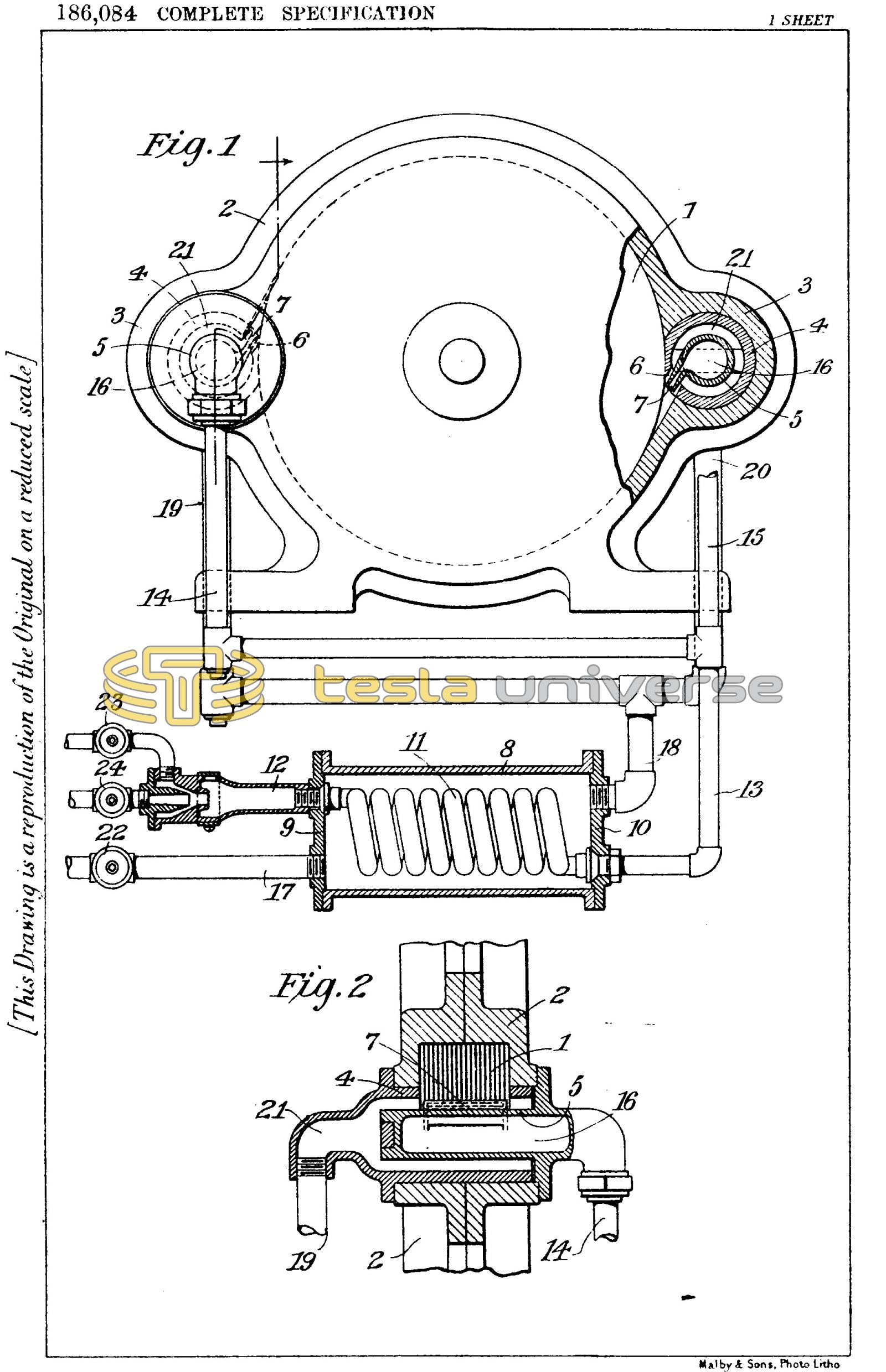
The preferred form of apparatus for carrying out the process above described is illustrated in the accompanying drawings in which Fig. 1 is a side view in elevation, partly cross-sectioned, and Fig. 2 a vertical section through one of the parts for supplying steam and combustion products to the turbine.
Referring to the figures more specifically, 1 is the rotor and 2, 2 the enclosing casing of the turbine which is provided with two diametrically opposite enlargements 3, 3 bored out and fitted with concentric conduits 4, 4 and 5, 5 for supplying the working fluids to the rotor. These are equipped with, or form part of, corresponding discharge nozzles 6, 6 and 7, 7. The superheater consists of a steam-chamber 8 closed at the ends by plates 9 and 10 and containing a coiled pipe 11, the ends of which are led out, one being connected to a combustion chamber 12 and the other to an outlet pipe 13 with branches 14 and 15 leading to the inner supply channels 16, 16. Steam inlet and outlet pipes, respectively, 17 and 18, are provided, the latter with two branches 19 and 20 communicating with channels 21, 21 of the supply part. Suitable steam, air and gas inlet valves, respectively marked 22, 23 and 24 may be employed for controlling and regulating the supply of the working fluids to the turbine. All the supply channels should be of a section sufficiently large so that the velocities of the fluids through them will be small as compared with those attained in the nozzles.
The operation will now be readily understood. Valves 23 and 24 being closed, the steam admitted by valve 22 passes through inlet pipe 17, chamber 8, outlet 18, branches 19 and 20, spaces 21, 21 and nozzles 6, 6, setting the turbine rotor in motion thus operating the machine as a simple steam turbine subject to the usual limitations in economic performance. The inlet valve 23 is now opened permitting the atmospheric air to be drawn in through coil 11, pipe 13, branches 14 and 15, channels 16, 16 and nozzles 7, 7 to the rotor. Power gas or other fuel is then admitted through valve 24 and upon being ignited in the combustion chamber 12 the products pass through in like manner, assisted by their initial velocity. As a result of this action, coiled pipe 11 is heated to a high temperature and superheats the steam in chamber 8 and also in the supply channels and nozzles, thus adding very materially to the available energy of the steam, at the same time increasing the efficiency of thermodynamic transformation. The products of combustion themselves, impinging against the rotor, contribute usefully some of their kinetic energy. The economic gain effected in this simple manner will be all the more pronounced the poorer the initial quality of the steam and the higher the pressure supply. However, low-pressure steam, as that exhausted from turbines or reciprocating engines, may likewise be economically utilized by this process and means, especially if provision is made for maintaining a vacuum at the exhaust end of the turbine.
The apparatus described is capable of minor modifications. For instance, the combustibles may be admitted to the rotor through the outer channels and steam through the inner ones. Again, the nozzles instead of being co-axial, as shown, may be otherwise constructed and disposed, or single nozzles may be used in their place and the mixture of the steam and gases effected before admission to them. However, this can be more or less completely accomplished with co-axial nozzles, as illustrated, merely by shortening one of them. As to the superheater it may be of widely varied design and incorporated with the turbine casing for the purpose of saving energy, weight and space. Departures may also be made in the design of the combustion chamber to suit the fuel employed and the necessary adjuncts for carburation and ignition will be provided, all of which, being well-known, are omitted from the drawing for the sake of clearness. Obviously, the process can be applied with more or less success in the transformation of the heat energy of elastic fluids other than steam.
This invention provides a self-starting, compact and efficient mixed-fluid turbine and will be found valuable on account of its extreme simplicity, low cost of instalment and the facilities it affords.
Having now particularly described and ascertained the nature of my said invention and in what manner the same is to be performed, I declare that what I claim is:-
- The hereinbefore described process of thermo-dynamic transformation of energy which consists in admitting steam to a turbine nozzle, aspirating by the suction thus created hot products of combustion through a heater, superheating the steam by them and discharging them at high velocity and in a direction parallel to the steam-jet upon the rotor, as described.
- The process of increasing the efficiency of steam as motive agent which consists in admitting it through a heater to a turbine nozzle, aspirating by the suction thus created hot products of combustion through the heater thereby raising the temperature of the steam to a high degree and discharging the products at high velocity and in contact with the steam-jet upon the rotor, as described.
- The method of operating a mixed fluid turbine which consists in starting it by steam admitted to the nozzle, aspirating by the suction produced in the space adjacent to the same hot products of combustion, superheating the steam by them and directing them upon the rotor so as to assist in driving it, as described.
- The herein described process and apparatus by which a turbine rotor is started by steam and combustible fluids are aspirated by the suction of the steam-jet into a combustion chamber, the products of combustion serving to superheat the steam and then assist in driving the rotor.
- In the process described and claimed in Claims 1, 2 and 3, the use of a friction turbine of very small windage.
- In the process and apparatus described and claimed in Claim 4, the use of concentric non-convergent nozzles opening directly into the rotor chamber of the turbine.
- In a mixed fluid turbine in which a secondary fluid is aspirated by the suction of the primary, the employment of non-convergent co-axial nozzles for discharging the fluids in parallel contacting streams upon the rotor, as described.
Dated the 23rd day of August, 1921.
Nikola Tesla.