Nikola Tesla Patents
Nikola Tesla British Patent 19,420 - Improvements in Alternating Current Electro-Magnetic Motors
[Third Edition.]
| No 19,420 | A.D. 1889 |
Date of Application, 3rd Dec., 1889 - Accepted, 11th Jan., 1890
COMPLETE SPECIFICATION.
[Communicated from abroad by Nikola Tesla, of the City and State of New York, United States of America, Electrician.]
Improvements in Alternating Current Electro-Magnetic Motors
I, Henry Harris Lake, of the firm of Haseltine, Lake & Co., Patent Agents, Southampton Buildings, in the County of Middlesex, do hereby declare the nature of this invention and in what manner the same is to be performed, to be particularly described and ascertained in and by the following statement:-
This invention relates to that form of alternating current motor in which there are two or more energizing circuits through which alternating currents differing in phase are caused to pass.
Various forms or types of this motor are now known to the public. First, motors having two or more energizing circuits of the same electrical character and in the operation of which the currents used differ primarily in phase. Second, motors with a plurality of energizing circuits of different electrical character, in or by means of which the difference of phase is produced artificially, and third, motors with a plurality of energizing circuits, the currents in one being induced from currents in another. The application of the present invention to these several types will be shown.
Considering the structural and operative conditions of any one of them, as for example that first named, the armature which is mounted to rotate in obedience to the cooperative influence or action of the energizing circuits, has coils wound upon it which are closed upon themselves, and in which currents are induced by the energizing currents with the object and result of energizing the armature core.
But under any such conditions as must exist in these motors, it is obvious that a certain time must elapse between the manifestations of an energizing current impulse in the field coils, and the corresponding magnetic state or phase in the armature established by the current induced thereby, consequently a given magnetic influence or effect in the field which is the direct result of a primary current impulse, will have become more or less weakened or lost before the corresponding effect in the armature, indirectly produced, has reached its maximum. This is a condition unfavorable to efficient working in certain cases, as, for instance, when the progress of the resultant poles or points of maximum, attraction is very great, or when a very high number of alternations is employed, for it is apparent that a stronger tendency to rotation will be maintained if the maximum magnetic attractions or conditions in both armature and field coincide, the energy developed by a motor being measured by the product of the magnetic quantities of the armature and field.
The object, therefore, in this invention is to so construct or organize these motors that the maxima of the magnetic effects of the two elements, the armature and field, shall more nearly coincide.
This is accomplished in various ways, which, may be best explained by reference to the drawings, in which various plans for accomplishing the desired results are illustrated.
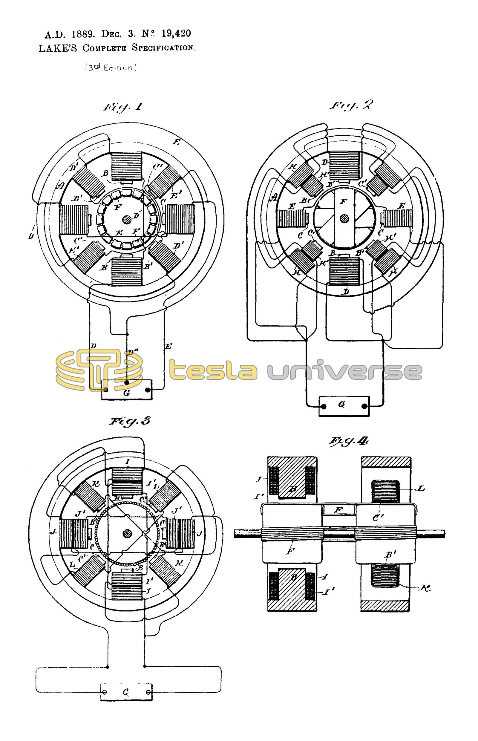
Figure 1. This is a diagrammatic illustration of a motor system in which the alternating currents proceed from independent sources and differ primarily in phase.
A designates the field, or magnetic frame of the motor, B, B, oppositely located pole pieces adapted to receive the coils of one energizing circuit and C, C, similar pole pieces for the coils of the other energizing circuit. These circuits are designated respectively by D, E, the conductor D11 forming a common return, to the generator G.
Between these poles is mounted an armature, for example a ring or annular armature wound with a series of coils F forming a closed circuit or circuits. The action or operation of a motor thus constructed is now well understood. It will be observed, however, that the magnetism of poles B, for example, established by a current impulse in the coils thereon precedes the magnetic effect set up in the armature by the induced current in coils F, consequently the mutual attraction between the armature and field poles is considerably reduced. The same conditions will, be found to exist, if, instead of assuming the poles B or C as acting independently, we regard the ideal resultant of both acting together, which is the real condition.
To remedy this the motor field is constructed with secondary poles B1 C1 which are situated between the others. These pole pieces are wound with coils D1 E1, the former in derivation to the coils D, the latter to coils E. The main or primary coils D and E are wound for a different self-induction from that of the coils D1 and E1, the relations being so fixed that if the currents in D and E differ, for example, by a quarter phase, the currents in each secondary coil as B1 C1 will differ from those in its appropriate primary B or C by say 45 degrees, or one eighth of a period.
The explanation of the action of this motor is as follows: Assuming that an impulse or alternation in circuit or branch E is just beginning while in the branch D it is just falling from maximum, - the conditions of a quarter phase difference; the ideal resultant of the attractive forces of the two sets of poles B, C, therefore may be considered as progressing from poles C to poles B while the impulse in E is rising to maximum and that in D is falling to zero or minimum. The polarity set up in the armature, however, lags behind the manifestations of field magnetism and hence the maximum points of attraction in armature and field instead of coinciding are angularly displaced. This effect is counteracted by the supplemental poles B1 C1. The magnetic phases of these poles succeed those of poles B C by the same, or nearly the same, period of time as elapses between the effect of the poles B C and the corresponding induced effect in the armature, hence the magnetic conditions of poles B1 C1 and of the armature more nearly coincide and a better result obtained. As poles B1 C1 act in conjunction with the poles in the armature established by poles B C, so in turn poles C B act similarly with the poles set up by B1 C1, respectively.
Under such conditions the retardation of the magnetic effect of the armature and that of the secondary poles will bring the maximum of the two more nearly into coincidence and a correspondingly stronger torque or magnetic attraction secured.
In such a disposition as is shown in Figure 1 it will be observed that as the adjacent pole pieces of either circuit are of like polarity they will have a certain weakening effect upon one another. It is therefore desirable to remove the secondary poles from the direct influence of the others. This may be done by constructing a motor with two independent sets of fields, and with either one or two armatures electrically connected, or by using two armatures and one field. These modifications will be illustrated hereinafter.
Figure 2 is a diagrammatic illustration of a motor and system in which the difference of phase is artificially produced.
There are two coils D D in one branch and two coils E E in the other branch of the main circuit from the generator G. These two circuits or branches are of different self induction, one, as D being higher than the other. For convenience this is indicated by making coils D much larger than coils E.
By reason of this difference in the electrical character of the two circuits the phases of current in one are retarded to a greater extent than the other. Let this difference be thirty degrees.
A motor thus constructed will rotate under the action of an alternating current, but as happens in the case previously described the corresponding magnetic effects of the armature and field do not coincide owing to the time that elapses between a given magnetic effect in the armature and the condition of the field that produces it. The secondary or supplemental poles B1 C1 are therefore employed.
There being a thirty degrees difference in phase between the currents in coils D E the magnetic effects of poles B1 C1 should correspond to that produced by a current differing from the current in coils D or E by 15 degrees. This may be accomplished by winding each supplemental pole B1 C1 with two coils H, H1. The coils H are included in a derived circuit having the same self-induction as circuit D and coils H1 in a circuit having the same self-induction as circuit E, so that if these circuits differ by 30 degrees the magnetism of poles B1 C1 will correspond to that produced by a current differing from that in either D or E by 15 degrees.
This is true in all other cases, for example, if in Figure 1 the coils D1 E1 be replaced by the coils H H1 included in derived circuits, the magnetism of the poles B1 C1 will correspond in effect or phase if it may be so termed, to that produced by a current differing from that in either circuit D or E by 45 degrees or one-eighth of a period.
This invention as applied to a derived circuit motor is illustrated in Figures 3 and 4. The former is an end view of the motor with the armature in section, and a diagram of connections, and Figure 4 a vertical section through the field.
These figures are also drawn to show one of the dispositions of two fields that may be adopted in carrying out the invention.
The poles B B, C C, are in one field, the remaining poles in the other. The former are wound with primary coils I J and secondary coils I1 J1, the latter with coils K L. The primary coils I J are in derived circuits between which, by reason of their different self-induction, there is a difference of phase, say of 30 degrees. The coils I1 K1 are in circuit with one another, as also are coils J1 l and there should be a difference of phase between the currents in coils K and L and their corresponding primaries of, say, 15 degrees.
If the poles B C are at right angles the armature coils should be connected directly across, or a single armature core wound from end to end may be used, but if the poles B C be in line there should be an angular displacement of the armature coils as will be well understood.
The operation will be understood from the foregoing. The maximum magnetic condition of a pair of poles as B1 B1 coincides closely with the maximum effect in the armature, which lags behind the corresponding condition in poles B B.
There are many other ways of carrying out this invention, but they all involve the same broad principle of construction and operation.
In using expressions herein to indicate a coincidence of the magnetic phases or effects in one set of field magnets with those set up in the armature by the other, approximate results only are meant, but this of course will be understood.
In these and similar motors the total energy supplied to effect their operation is equal to the sum of the energies expended in the armature and the field.
The power developed, however, is proportionate to the product of these quantities. This product will be greatest when these quantities are equal, hence, in constructing a motor it is desirable to determine the mass of the armature and field cores and the windings of both and adapt the two so as to equalize as nearly as possible the magnetic quantities of both.
In motors which have closed armature coils, this is only approximately possible as the energy manifested in the armature is the result of inductive action from the other element, but in motors in which the coils of both armature and field are connected with the external circuit, the result can be much more perfectly obtained.
In further explanation of this object let it be assumed that the energy as represented in the magnetism in the field of a given motor is 90 and that of the armature 10. The sum of these quantities which represents the total energy expended in driving the motor is 100. But assume that the motor be so constructed that the energy in the field is represented by 50, and that in the armature by 50, the sum is still 100, but while in the first instance the product is 900, in the second it is 2,500, and as the energy developed is in proportion to these products, it is clear that those motors are the most efficient, other things being equal, in which the magnetic energies developed in the armature and field are equal.
These results may be obtained by using the same amount of copper or ampere turns in both elements, when the cores of both are equal or approximately so, and the same current energizes both. Or, in cases where the currents in one element are induced by those of the other, by using in the induced coils an excess of copper over that in the primary element or conductor.
Having now particularly described and ascertained the nature of the said invention and in what manner the same is to be performed as communicated to me by my foreign correspondent I declare that what I claim is,-
- In an alternating current motor the combination with an armature wound with closed coils, of main and supplemental field magnets or poles, one set of which is adapted to exhibit their maximum magnetic effect simultaneously with that set up in the armature by the action of the other, as set forth.
- In an electro-magnetic motor the combination with an armature of a plurality of field or energizing coils included respectively in main circuits adapted to produce a given difference of phase and supplementary or secondary circuits adapted to produce an intermediate difference of phase, as set forth.
- An electro-magnetic motor in which the field and armature magnets exhibit equal strength or magnetic quantities under the influence of a given energizing current, as set forth.
- In an alternating current motor, the combination with field and armature cores of equal mass of energizing coils containing equal amounts of copper as herein set forth.
Dated this 3rd day of December 1889.
Haseltine, Lake & Co.,
45, Southampton Buildings, London, Agents for the Applicant.