Nikola Tesla Patents
Nikola Tesla British Patent 20,981 - Improvements Relating to the Production, Regulation, and Utilization of Electric Currents of High Frequency, and to Apparatus Therefor
| No 20,981 | A.D. 1896 |
Date of Application, 22nd Sept., 1896 - Accepted, 21st Nov., 1896
COMPLETE SPECIFICATION.
[Communicated from abroad by Nikola Tesla, of 46 East Houston Street, New York, United States of America, Electrician.]
Improvements Relating to the Production, Regulation, and Utilization of Electric Currents of High Frequency, and to Apparatus Therefor.
I, Henry Harris Lake, of the Firm of Haseltine, Lake & Co., Patent Agents, 45 Southampton Buildings, in the County of Middlesex, do hereby declare the nature of this invention and in what manner the same is to be performed, to be particularly described and ascertained in and by the following statement:-
This invention, subject of the present application, is embodied in certain improvements in methods of and apparatus for producing, regulating and utilizing electric currents of high frequency heretofore invented by Nikola Tesla, and described in British Letters Patent No. 8575, dated May 19, 1891. The method and apparatus referred to in said patent were devised for the purpose of converting, supplying and utilizing electrical energy in a form suited for the production of certain novel electrical phenomena which require currents of high potential and a higher frequency than can readily or even possibly, be developed by generators of the ordinary types or by such mechanical appliances as were theretofore known. The invention referred to was based upon the principle of charging a condenser or a circuit possessing capacity and discharging the same, generally through the primary of a transformer, the secondary of which constituted the source of working current, and under such conditions as to yield a vibratory or rapidly intermittent discharge current.
The present invention, while aiming to simplify and render more efficient the apparatus heretofore used, has for its object, primarily, to provide a means for converting such currents as are generally and most readily obtainable from the mains of ordinary systems of municipal distribution, into currents of the special character referred to, and to regulate or control, and utilize such currents in a simple, economical and efficient manner. The improvements are illustrated herein in forms of apparatus adapted for use with existing circuits or systems, and which while constructed and operating on the same general principles are modified only as may be required by a direct or an alternating source of supply.
The apparatus by which the present improvements are carried out may be described in general terms as comprising a circuit from a given source of supply, in which is included or with which is connected any suitable device for making and breaking such circuit in the manner desired, a condenser arranged so as to be periodically charged by the said circuit through the instrumentality of the circuit controller, and a circuit, through which the condenser discharges, of such character that the discharge will take place in a series of rapidly recurring or intermittent impulses.
In the drawings which illustrate the invention,
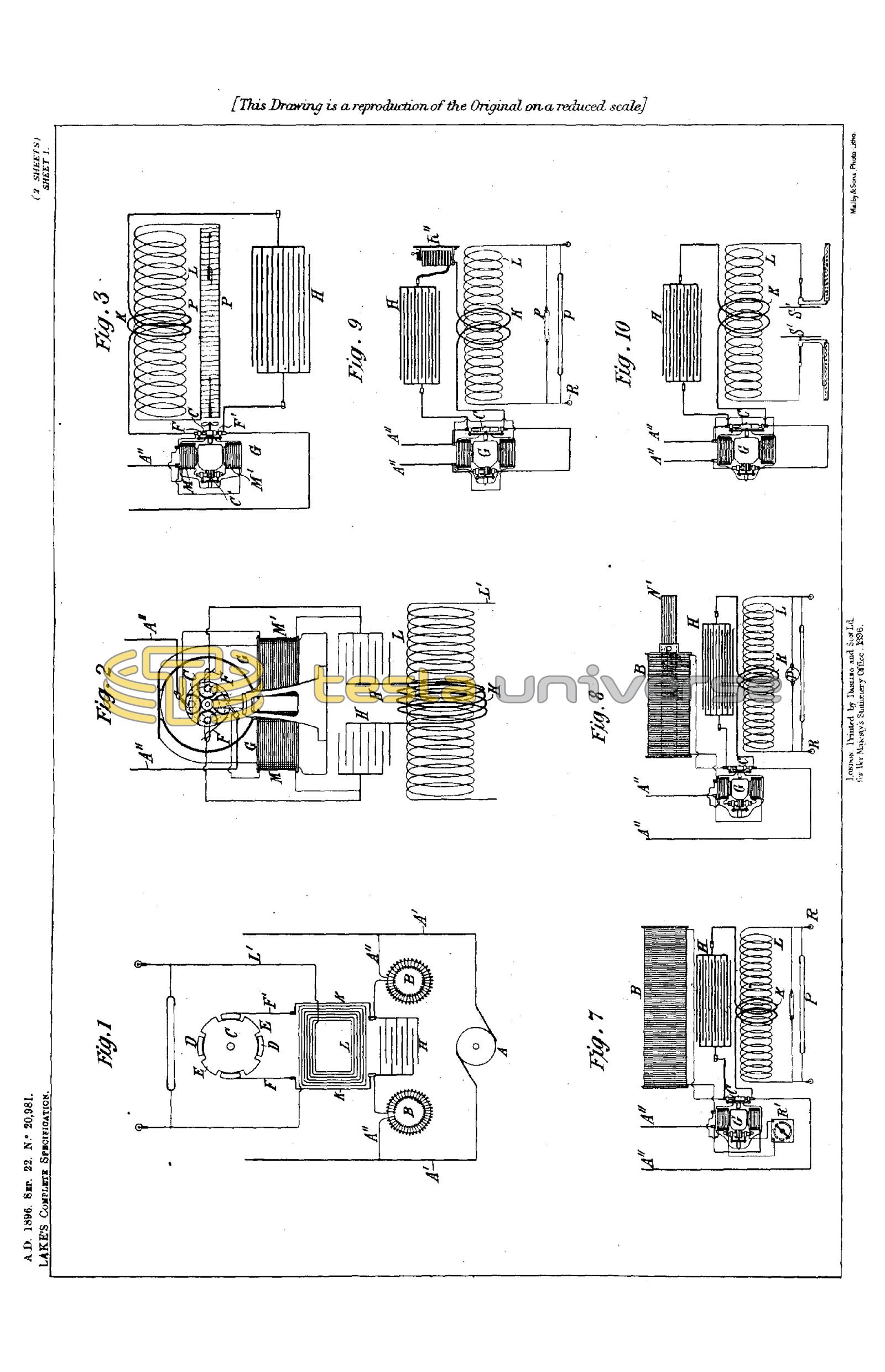
Fig. 1 is a diagram of circuits and apparatus employed with a source of direct currents. Figs. 2 and 3 are modifications of the same.
Figs. 4, 5 and 6 illustrate the apparatus and circuit connections employed with a source of alternating current. Figs. 7, 8, 9, 10 are similar views illustrating the method of and apparatus for regulating the system.
Figs. 11, 12, 13, 14 and 15 are views illustrating a form of circuit controller for use with the system and the manner of connecting up and using the same.
When the apparatus is to be employed for the purpose of converting a direct current of comparatively low potential into one of high frequency, a device in the nature of a choking coil is interposed in the circuit, in order that advantage may be taken of the discharge of high electro-motive force, which is manifested at each break of such circuit for charging a condenser.
It will be apparent from a consideration of the conditions involved, that were the condenser to be directly charged by the current from the source and then discharged into its local or discharging circuit, a very large capacity would ordinarily be required, but by the introduction into the charging circuit of a high self induction the current of high electro-motive force which is induced at each break of said circuit, furnishes the proper current for charging the condenser, which may, therefore, be small and inexpensive.
Figures 1 and 2 illustrate that part of the improvement which relates to the conversion of direct or continuous current. Referring to said figures, A designates any source of direct current. In any branch of the circuit from said source, such, for example, as would be formed by the conductors A11 A11 from the mains A1 A1, and the conductors K K are placed self induction or choking coils B B and any proper form of circuit controlling device as C. This device in the present instance is shown as an ordinary metallic disk or cylinder with teeth or separated segments D D, E E, of which one or more pairs as E E, diametrically opposite, are integral or in electrical contact with the body of the cylinder, so that when the controller is in the position in which the two brushes F, F1, bear upon two of said segments E E, the circuit through the choking coils B B will be closed. The segments D, D, are insulated, and while shown in the drawings as of substantially the same length of arc as the segments E E, this latter relation may be varied at will to regulate the periods of charging and discharging.
The controller is designed to be rotated by any proper device, such for example, as an electro-magnetic motor, as shown in Figure 2, receiving current either from the main source or elsewhere.
Around the controller C or in general having its terminals connected with the circuit on opposite sides of the point of interruption, is a condenser H, or a circuit of suitable capacity, and in series with the latter the primary K of a transformer, the secondary L of which constitutes the source of the currents of high frequency. L1 indicates the circuit from the secondary and may be regarded as the working circuit.
It will be observed that since the self induction of the circuit through which the condenser discharges, as well as the capacity of the condenser itself, may be given practically any desired value, the frequency of the discharge current may be adjusted at will.
In the operation of this apparatus the controller closes the charging circuit and then interrupts the same. When the break occurs the accumulated energy in the said circuit charges the condenser. Then while the charging circuit is again completed, the condenser discharges through the primary K, by a succession of rapid impulses. These operations are maintained by the action of the controller.
A more convenient and simplified arrangement of the apparatus is shown in Figure 2. In this case the small motor G which drives the controller has its field coils M M1 in derivation to the main circuit, and the controller C and condenser H, are in parallel in the field circuit between the two coils. In such case the field coils M M1 take the place of the choking coils B.
In this arrangement, and in fact, generally, it is preferable to use two condensers or a condenser in two parts, and to arrange the primary coil of the transformer between them. The interruption of the field circuit of the motor should be so rapid as to permit only a partial demagnetization of the cores; these latter, moreover, should in this specific arrangement, be laminated.
In lieu of connecting the field coils of the motor only with the charging circuit to raise the self induction therein, the motor may be connected in other ways, that is to say, its armature only may be connected with the circuit, or its field and armature coils may be in series and both connected with such circuit. This latter arrangement is illustrated in Figure 3, in which a terminal of the circuit A11 is connected to one of the binding posts of the motor from which the circuit is led through one field coil M, the brushes and commutator C1 and the other field coil M1, and thence to a brush F which rests upon the controller disk or cylinder C. The other terminal of the circuit connects with a second brush F1 bearing on the controller, so that the current which passes through and operates the motor is periodically interrupted.
As an illustration of the various uses to which the apparatus may be put, the secondary L is shown in this figure as connected to two plates P, P, of any suitable character between which a current of air is maintained by a fan on the shaft of the motor G, for developing ozone or for similar purposes.
When the potential of the source of current periodically rises and falls, whether with reversals or not is immaterial, it is essential to economical operation that the intervals of interruption of the charging circuit should bear a definite time relation to the period of the current, in order that the effective potential of the impulses charging the condenser may be as high as possible. In case, therefore, an alternating or equivalent electromotive force be employed as the source of supply, a circuit controller is used which will interrupt the charging circuit at instants predetermined with reference to the variations of potential therein.
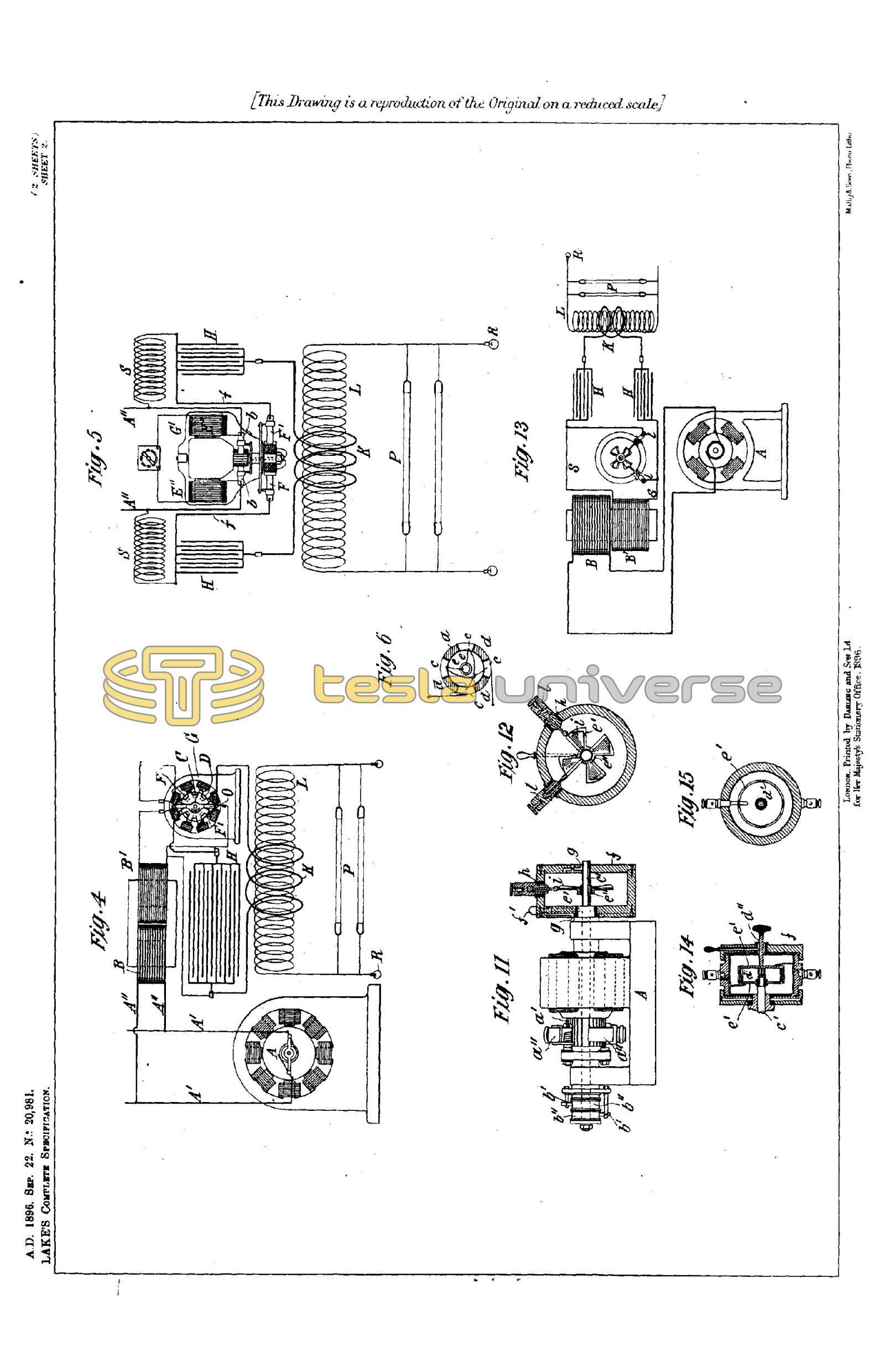
A convenient, and probably the most practicable means for accomplishing this is a synchronous motor connected with the source of supply and operating a circuit controller which first interrupts the charging current at or about the instant of highest intensity of each wave and then permits the condenser to discharge the energy stored in it, through its appropriate circuit. Such apparatus, which may be regarded as typical of the means for accomplishing this purpose, is illustrated in Figures 4, 5 and 6.
In Fig. 4, A11 A11 are the conductors taken from the mains of any alternating current generator A, and for raising the potential of such current a transformer is employed represented by the primary B and secondary B1.
The circuit of the secondary includes the energizing coils of a synchronous motor G, and a circuit controller C fixed to the shaft of the motor.
An insulating arm O, stationary with respect to the motor shaft and adjustable with reference to the poles of the fixed magnets, carries two brushes F F1 which bear upon the periphery of the disk C. With the parts thus arranged, the secondary circuit is completed through the coils of the motor whenever the two brushes rest upon the uninsulated segments of the disk, and interrupted through the motor at other times.
Such a motor, if properly constructed, in well understood ways, maintains very exact synchronism with the alternations of the source, and the arm O may, therefore, be adjusted to interrupt the current at any determined point of its waves. By the proper relations of insulated and conducting segments, and the motor poles, the current may be interrupted twice in each complete wave at or about the points of highest intensity.
In order that the energy stored in the motor circuit may be utilized at each break to charge the condenser H, the terminals of the latter are connected to the two brushes F F1 or to points of the circuit adjacent thereto, so that when the circuit through the motor is interrupted the terminals of the motor circuit will be connected with the condenser. The discharge of the condenser takes place through the primary K, the circuit of which is completed simultaneously with the motor circuit and interrupted while the motor circuit is broken and the condenser being charged. The secondary impulses of high potential and great frequency are available for the operation of vacuum tubes P, single terminal lamps R, and other novel and useful purposes.
It is obvious that the supply current need not be alternating, provided it be converted or transformed into an alternating current, before reaching the controller. For example, the present improvements are applicable to various forms of rotary transformers as is illustrated in Figs. 5 and 6.
G1 designates a continuous current motor, here represented as having four field poles wound with coils E11 in shunt to the armature. The line wires A11 A11 connect with the brushes b b bearing on the usual commutator.
On an extension of the motor shaft is a circuit controller composed of a cylinder, the surface of which is divided into four conducting segments c, and four insulating segments d, the former being diametrically connected in pairs as shown in Fig. 6.
Through the shaft run two insulated conductors e e from any two commutator segments ninety degrees apart, and these connect with the two pairs of segments c, respectively. With such arrangement, it is evident that any two adjacent segments c c become the terminals of an alternating current source, so that if two brushes F F1 be applied to the periphery of the cylinder they will take off current during such portion of the wave as the width of segment and position of the brushes may determine. By adjusting the position of the brushes relatively to the cylinder, therefore, the alternating current delivered to the segments c c may be interrupted at any point of its waves.
While the brushes F F1 are on the conducting segments the current which they collect stores energy in a circuit of high self-induction formed by the wires f f, self-induction coils S S, the conductors A11 A11, the brushes and commutator. When this circuit is interrupted by the brushes F F1, passing onto the insulating segments of the controller, the high potential discharge of this circuit stores energy in the condensers H H which then discharge through the circuit of low self-induction containing the primary K. The secondary circuit contains any devices as P, R, for utilizing the current.
In some cases the energy delivered by the system may be readily and economically regulated. It is well known that every electric circuit, provided its ohmic resistance does not exceed certain definite limits, has a period of vibration of its own analogous to the period of vibration of a weighted spring. In order to alternately charge a given circuit of this character by periodic impulses impressed upon it and to discharge it most effectively, the frequency of the impressed impulses should bear a definite relation to the frequency of vibration possessed by the circuit itself. Moreover, for like reasons, the period of vibration of the discharge circuit should bear a similar relation to the impressed impulses or the period of the charging circuit. When the conditions are such that the general law of harmonic vibrations is followed, the circuits are said to be in resonance or in electro-magnetic synchronism, and this condition of the system is found to be highly advantageous.
In carrying out the invention, therefore, the electrical constants should be so adjusted that in normal operation the condition of resonance is approximately attained. To accomplish this, the number of impulses of current directed into the charging circuit per unit time is made equal to the period of the charging circuit itself, or, generally, to a harmonic thereof, and the same relations are maintained between the charging and discharge circuit. Any departure from this condition will result in a decreased output, and this fact is taken advantage of in regulating such output by varying the frequencies of the impulses or vibrations in the several circuits.
Inasmuch as the period of any given circuit depends upon the relations of its resistance, self-induction and capacity, a variation of any one or more of these may result in a variation in its period. There are, therefore, various ways in which the frequencies of vibration of the several circuits in the system may be varied, but the most practicable and efficient ways of accomplishing the desired result are the following:
(a) Varying the rate of the impressed impulses or those which are directed from the source of supply into the charging circuit, as by varying the speed of the commutator or other circuit controller.
(b) Varying the self-induction of the charging circuit.
(c) Varying the self-induction or capacity of the discharge circuit.
To regulate the output of a single circuit which has no vibration of its own, by merely varying its period would evidently require, for any extended range of regulation, a very wide range of variation of period. But in the system described, a very wide range of regulation of the output may be obtained by a very slight change of the frequency of one of the circuits when the above mentioned rules are observed.
Figs. 7, 8, 9 and 10 illustrate some of the more practicable means for effecting the regulation, as applied to a system deriving its energy from a source of direct currents.
In each of the figures A11 A11 designate the conductors of a supply circuit of continuous current, G a motor connected therewith in any of the usual ways, and operating a current controller C which serves to alternately close the supply circuit through the motor or through a self-induction coil, and to connect such motor circuit with a condenser H, the circuit of which contains a primary coil K, in proximity to which is a secondary coil L serving as the source of supply to the working circuit or that in which are connected up the devices P R for utilizing the current.
In order to secure the greatest efficiency in a system of this kind, it is essential, as before stated, that the circuits, which mainly as a matter of convenience are designated as the charging and the discharge circuits, should be approximately in resonance or electro-magnetic synchronism. Moreover, in order to obtain the greatest output from a given apparatus of this kind it is desirable to maintain as high a frequency as possible.
The electrical conditions, which are now well understood, having been adjusted to secure, as far as practical considerations will permit, these results, the regulation of the system is effected by adjusting its elements so as to depart in a greater or less degree from the above conditions with a corresponding variation of output. For example, as in Figure 7 the speed of the motor, and consequently of the controller, may be varied in any suitable manner, as by means of a rheostat R1 in a shunt to such motor, or by shifting the position of the brushes on the main commutator of the motor or otherwise. A very slight variation in this respect by disturbing the relations between the rate of impressed impulses and the vibration of the circuit of high self-induction into which they are directed, causes a marked departure from the condition of resonance and a corresponding reduction in the amount of energy delivered by the impressed impulses to the apparatus.
A similar result may be secured by modifying any of the constants of the local circuits as above indicated. For example, in Figure 8 the choking coil B is shown as provided with an adjustable core N1, by the movement of which into and out of the coil the self-induction, and consequently the period of the circuit containing such coil, may be varied.
As an example of the way in which the discharge circuit or that into which the condenser discharges, may be modified to produce the same result, there is shown in Figure 9 an adjustable self-induction coil R11 in the circuit with the condenser, by the adjustment of which coil the period of vibration of such circuit may be changed.
The same result would be secured by varying the capacity of the condenser, but if the condenser were of relatively large capacity this might be an objectionable plan, and a more practicable method is to employ a variable condenser in the secondary or working circuit, as shown in Figure 10. As the potential in this circuit is raised to a high degree, a condenser of very small capacity may be employed, and if the two circuits, primary and secondary, are very intimately and closely connected, the variation of capacity in the secondary is similar in its effects to the variation of the capacity of the condenser in the primary. As a means well adapted for this purpose two metallic plates S1 S1 adjustable to and from each other and constituting the two armatures of the condenser are shown.
The description of the means of regulation is confined herein to a source of supply of direct current, for to such it more particularly applies, but it will be understood that if the system be supplied by periodic impulses from any source which will effect the same results, the regulation of the system may be effected by the method herein described.
The circuit controller or the device which ensures the proper charging and discharging of the condenser may be of any construction that will perform the functions required of it. In illustration of the principle of construction and mode of operation, reference has been made only to forms of mechanism that make and break metallic contacts, but there need be no actual metallic contact, if provision be made for the passage of a spark between separated conductors. Such a device is illustrated in Figs. 11 to 15.
A designates, in Fig. 11, a generator having a commutator a1 and brushes a11 bearing thereon, and also collecting rings b11, b11, from which an alternating current is taken by brushes b1 in the well understood manner.
The circuit controller is mounted, in part, on an extension of the shaft c 1of the generator, and in part on the frame of the same, or on a stationary sleeve surrounding the shaft. Its construction, in detail, is as follows: -
e1 is a metal plate with a central hub e11 which is keyed or clamped to the shaft c1. The plate is formed with segmental extensions corresponding in number to the waves of current which the generator delivers. These segments are preferably cut away, leaving only rims or frames, to one of the radial sides of which are secured bent metal plates i which serve as vanes to maintain a circulation of air when the device is in operation.
The segmental disk and vanes are contained within a close insulated box or case f mounted on the bearing of the generator, or in any other proper way, but so as to be capable of angular adjustment around the shaft. To facilitate such adjustment, a screw rod f1, provided with a knob or handle, is shown as passing through the wall of the box. The latter may be adjusted by this rod, and when in proper position may be held therein by screwing the rod down into a depression in the sleeve or bearing as shown in Fig. 11.
Air passages g g are provided at opposite ends of the box through which air is maintained in circulation by the action of the vanes.
Through the sides of the box f, and through insulating gaskets h, when the material of the box is not a sufficiently good insulator, extend metallic terminal plugs l, l, with their ends in the plane of the conducting segmental disk e1 and adjustable radially towards and from the edges of the segments.
Devices of this character are employed in the manner illustrated in Fig. 13.
A, in this figure, represents any source of alternating current, the potential of which is raised by a transformer of which B is the primary and B1 the secondary.
The ends of the secondary circuit s are connected to the terminal plugs l, l, of an apparatus similar to that of Figures 11 and 12, and having segments rotating in synchronism with the alternations of the current source, preferably, as above described, by being mounted on the shaft of the generator, when the conditions so permit.
The plugs l, l, are then adjusted radially so as to approach more or less the path of the outer edges of the segmental disk, and so that during the passage of each segment in front of a plug a spark will pass between them, which completes the secondary circuit, s. The box, or the support for the plugs l, is adjusted angularly so as to bring the plugs and segments into proximity at the desired instants with reference to any phase of the current wave in the secondary circuit, and fixed in position in any proper manner.
To the plugs l, l, are also connected the terminals of a condenser or condensers, so that at the instant of the rupture of the secondary circuit s by the cessation of the sparks the energy accumulated in such circuit will rush into, and charge, the condenser.
A path of low self-induction and resistance, including a primary K of a few turns, is provided to receive the discharge of the condenser, when the circuit s is again completed by the passage of sparks, the discharge being manifested as a succession of extremely rapid impulses.
By means of this apparatus effects of a novel and useful character are obtainable, but to still further increase the efficiency of the discharge or working current, there may be in some instances provided a means for further breaking up the individual sparks themselves. A device for this purpose is shown in Figures 14 and 15.
The box or case f in these figures is fixedly secured to the frame or bearing of the generator or motor which rotates the circuit controller in synchronism with the alternating source. Within said box is a disk e1 fixed to the shaft c1 with projections d1 extending from its edge parallel with the axis of the shaft. A similar disk e1 on a spindle d11 in face of the first is mounted in a bearing in the end of the box f with a capability of rotary adjustment.
The ends of the projections d1 are deeply serrated or several pins or narrow projections placed side by side, as shown in Fig. 14, so that as those of the opposite disks pass each other a rapid succession of sparks will pass from the projections of one disk to those of the other.
The invention is not limited to the precise devices or forms of the devices shown and described. For example, when the source of supply is a circuit of high self-induction no special choking coils or the like need be employed. So, too, the condenser as a distinctive apparatus may be dispensed with when the capacity of its circuit is sufficiently great to accomplish the desired result. The circuit controller may, as already explained, be very greatly modified and varied in construction and principle of operation without departure from the invention.
In the illustrations given of the circuit controller, the contacts and insulating spaces are arranged for charging and discharging a single condenser, but it is obvious that a single motor and circuit controller may be used to operate more than one condenser, by charging one while discharging the other or others.
Having now particularly described and ascertained the nature of the said invention and in what manner the same is to be performed, as communicated to me by my foreign correspondent, I declare that what I claim is:-
- The apparatus herein described for converting electric currents of the kind generally obtainable from municipal systems of electric distribution, into currents of high frequency, comprising in combination a circuit of high self-induction, a circuit controller adapted to make and break such circuit, a condenser into which the said circuit discharges when interrupted, and a transformer through the primary of which the condenser discharges, as set forth.
- The combination with a circuit of high self-induction and means for making and breaking the same, of a condenser around the point of interruption in the said circuit, and a transformer the primary of which is in the condenser circuit, as described.
- The combination with a circuit having a high self-induction, of a circuit controller for making and breaking said circuit, a motor for driving the controller, a condenser in a circuit connected with the first around the point of interruption therein, and a transformer the primary of which is in circuit with the condenser, as set forth.
- The combination with an electric circuit of a controller for making and breaking the same, a motor included in or connected with said circuit so as to increase its self-induction and driving the said controller, a condenser in a circuit around the controller, and a transformer through the primary of which the condenser discharges, as set forth.
- The combination with a circuit of direct current, of a controller for making and breaking the same, a motor having its field or armature coils or both included in said circuit and driving said controller, a condenser connected with the circuit around the point of interruption therein, and a transformer, the primary of which is in the discharge circuit of the condenser, as set forth.
- The method herein described of converting alternating currents of relatively low frequency into currents of high frequency, which consists in charging a condenser by such currents of low frequency during determinate intervals of each wave of said current, and discharging the condenser through a circuit of such character as to produce therein a rapid succession of impulses, as set forth.
- The combination with a source of alternating current, a condenser, a circuit controller adapted to direct the current during determinate intervals of each wave into the condenser for charging the same, and a circuit into which the condenser discharges, as set forth.
- The combination with a source of alternating current, a synchronous motor operated thereby, a circuit controller operated by the motor and adapted to interrupt the circuit through the motor at determinate points in each wave, a condenser connected with the motor circuit and adapted on the interruption of the same to receive the energy stored therein, and a circuit into which the condenser discharges, as set forth.
- The combination with a source of alternating current, a charging circuit in which the energy of said current is stored, a circuit controller adapted to interrupt the charging circuit at determinate points in each wave, a condenser, for receiving on the interruption of the charging circuit, the energy accumulated therein, and a circuit into which the condenser discharges when connected therewith by the circuit controller, as set forth.
- The method of regulating the energy delivered by a system for the production of high frequency currents, and comprising a supply circuit, a condenser, a circuit through which the same discharges, and means for controlling the charging of the condenser by the supply circuit and the discharging of the same, the said method consisting in varying the relations of the frequencies of the impulses in the circuits comprising the system, as set forth.
- The method of regulating the energy delivered by a system for the production of high frequency currents comprising a supply circuit of direct currents, a condenser adapted to be charged by the supply circuit and to discharge through another circuit, the said method consisting in varying the frequency of the impulses of current from the supply circuit, as set forth.
- The method of producing and regulating electric currents of high frequency which consists in directing impulses from a supply circuit into a charging circuit of high self-induction, charging a condenser by the accumulated energy of such charging circuit, discharging the condenser through a circuit of low self-induction, raising the potential of the condenser discharge and varying the relations of the frequencies of the electrical impulses in the said circuits, as set forth.
- The combination with a source of current, of a condenser adapted to be charged thereby, a circuit into which the condenser discharges in a series of rapid impulses, and a circuit controller for effecting the charging and discharge of said condenser, composed of conductors movable into and out of proximity with each other, whereby a spark may be maintained between them and the circuit closed thereby during determined intervals, as set forth.
- The combination with a source of alternating current, of a condenser adapted to be charged thereby, a circuit into which the condenser discharges in a series of rapid impulses, and a circuit controller for effecting the charging and discharge of said condenser composed of conductors movable into and out of proximity with each other in synchronism with the alternations of the source, as set forth.
- A circuit controller for systems of the kind described, comprising in combination a pair of angularly adjustable terminals and two or more rotating conductors mounted to pass in proximity to the said terminals, as set forth.
- A circuit controller for systems of the kind described, comprising in combination two sets of conductors, one capable of rotation and the other of angular adjustment whereby they may be brought into and out of proximity to each other at determinate points and one or both being subdivided so as to present a group of conducting points, as set forth.
Dated this 22nd day of September 1896.
Haseltine, Lake & Co.,
45 Southampton Buildings, London, W.C.,
Agents for the Applicant.