Nikola Tesla Patents
Nikola Tesla British Patent 8575 - Improved Methods of and Apparatus for Generating and Utilizing Electric Energy for Lighting Purposes
| No 8575 | A.D. 1891 |
Date of Application, 19th May, 1891 - Accepted 20th June, 1891
COMPLETE SPECIFICATION.
Improved Methods of and Apparatus for Generating and Utilizing Electric Energy for Lighting Purposes
I, Nikola Tesla, of the Gerlach, 45 West 27th Street, New York, United States of America, Electrician, do hereby declare the nature of this invention and in what manner the same is to be performed to be particularly described and ascertained in and by the following statement:-
My invention consists in a novel method of, and apparatus for producing light by electricity, as hereinafter described.
Electric currents of very great frequency or of very short duration and also electric currents of very great difference of potential have heretofore been produced for various purposes, but I have discovered that results of the most useful character may be secured by means of electric currents in which both the above described conditions of great frequency and great difference of potential are present. In other words, I have found that an electrical current of an excessively small period and very high potential may be utilized economically and practically to great advantage for the production of light, and I would here make it clear that I refer now to a current or what may be termed an electrical effect, of a rapidity of oscillation or alternation far in excess of anything that has heretofore been considered desirable or perhaps possible under practical working conditions, and of a potential greater, perhaps, than has ever been developed and applied to any useful purpose, and this will be more fully disclosed by the description of the nature of the invention which is hereinafter given.
The carrying out of this invention and the full realization of the conditions necessary to the attainment of the desired results involve, first a novel method of and apparatus for producing the currents or electrical effects of the character described, second, a novel method of utilizing and applying the same for the production of light, and third, a new form of translating device or light giving appliance.
To produce a current of very high frequency and very high potential, certain well-known devices may be employed. For instance, as the primary source of current or electrical energy a continuous current generator may be used, the circuit of which may be interrupted with extreme rapidity by mechanical devices, or, a magneto-electric machine specially constructed to yield alternating currents of very small period may be used, and in either case should the potential be too low, an induction coil may be employed to raise it. Or, finally in order to overcome the mechanical difficulties, which in such cases become practically insuperable before the best
results are reached, the principle of the disruptive discharge may be utilized. By means of this latter plan a much greater rate of change in the current is produced, and the invention, though not limited to this plan, will be illustrated by a description of the same.
The current of high frequency, therefore, that is necessary to the successful working of the invention is produced by the disruptive discharge of the accumulated energy of a condenser maintained by charging the said condenser from a suitable source of current and discharging it into or through a circuit under proper relations of self-induction, capacity resistance and period in the well understood ways. Such a discharge is known to be, under proper conditions, intermittent or oscillating in character, and in this way a current varying in strength at an enormously rapid rate may be produced.
Having produced in the above manner a current of excessive frequency, I obtain from it, by means of an induction coil, enormously high potentials. That is to say, in the circuit through which or into which the disruptive discharge of the condenser takes place, I include the primary of a suitable induction coil, and by a secondary coil of much longer and finer wire I convert to currents of extremely high potentials. The differences in the length of the primary and secondary coils, in connection with the enormously rapid rate of change in the primary current, yield a secondary of enormous frequency and excessively high potential.
Such currents are not, so far as I am aware, available for use in the usual way. But I have discovered that if I connect to either of the terminals of the secondary coil or source of current of high potential the leading-in wires of such a device for example, as an ordinary incandescent lamp, that the carbon may be brought and maintained at incandescence, or, in general, that any body capable of conducting the high tension current described and properly enclosed in a rarefied or exhausted receiver may be rendered luminous or incandescent, either when connected directly with one terminal of the secondary source of energy or placed in the vicinity of such terminals so as to be acted upon inductively.
Without attempting a detailed explanation of the causes to which the phenomenon may be ascribed, it is sufficient to state, that assuming the now generally accepted theories of scientists to be correct, the effects thus produced are attributable to molecular bombardment, condenser action and electric or etheric disturbances.
Whatever part each or any of these causes may play in producing the effect noted, it is, however, a fact that a strip of carbon, or a mass of any other shape either of carbon or any more or less conducting substance in a rarefied or exhausted receiver and connected directly or inductively to a source of electrical energy such as described, may be maintained at incandescence if the frequency and potential of the current be sufficiently high. It may be here stated that by the term “currents of high frequency and high potential” and similar expressions used in this description is not meant necessarily, currents in the usual acceptance of the term, but, generally speaking, electrical disturbances or effects such as would be produced in the secondary source by the action of the primary disturbance of electrical effect.
It is necessary to observe in carrying out this invention that care must be taken to reduce to a minimum, the opportunity for the dissipation of the energy from the conductors, intermediate to the source of current and the light-giving body. For this purpose the conductors should be free from projections and points and well covered or coated with a good insulator.
The body to be rendered incandescent should be selected with a view to its capability of withstanding the action to which it is exposed without being rapidly destroyed, for some conductors will be much more speedily consumed than others.
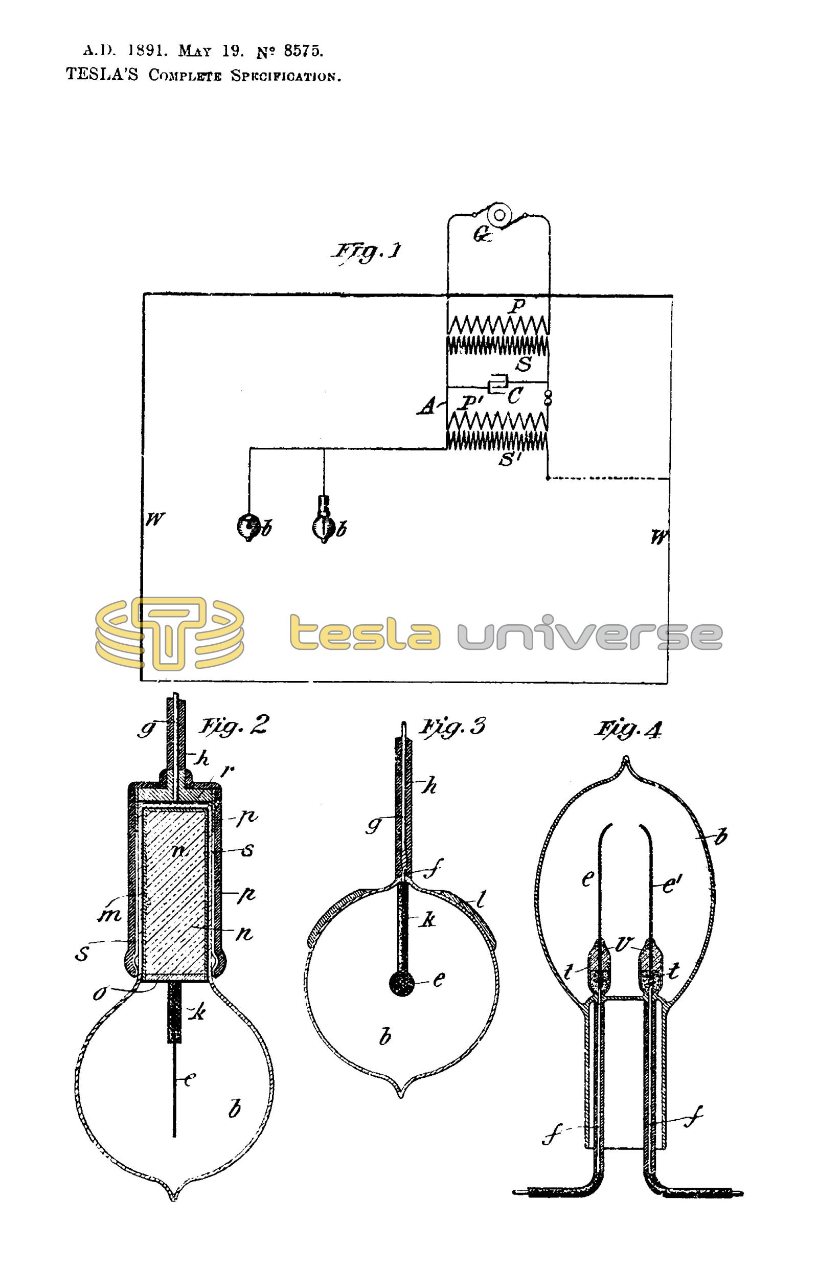
In the accompanying drawing,
Figure 1 is a diagram of one of the special arrangements which I employ for carrying my invention into practice.
Figures 2, 3 and 4 are vertical sectional views of modified forms of light-giving devices that I have devised for use with the improved system.
As all of the apparatus herein shown, with the exception of the special forms of lamp, is or may be of well-known construction and in common use for other purposes, it is indicated mainly by conventional representations.
G is the primary source of current of electrical energy. I have explained above how various forms of generator might be used for this purpose, but in the present illustration I assume that G is an alternating current generator of comparatively low electro-motive force. Under such circumstances, I raise the potential of the current by means of an induction coil having a primary P and secondary S. Then, by the current developed in this secondary, I charge a condenser C, and this condenser I discharge through or into a circuit A having an air gap a, or in general, means for maintaining a disruptive discharge.
By the means above described, a current of enormous frequency is produced. My object is next to convert this into a working circuit of very high potential for which purpose I connect up in the circuit A the primary P1 of an induction coil having a long fine wire secondary S1. The current in the primary P1 develops in the secondary S1 a current or electrical effect of corresponding frequency but of enormous difference of potential, and the secondary S1 thus becomes the source of the energy to be applied to the purpose of producing light.
The light-giving devices may be connected to either terminal of the secondary S1. If desired, one terminal may be connected to a conducting wall W of a room or space to be lighted, and the other arranged for connection of the lamps therewith. In such case the walls should be coated with some metallic or conducting substance in order that they may have sufficient conductivity. The lamps or light-giving devices may be an ordinary incandescent lamp, but I prefer to use specially designed lamps, examples of which I have shown in detail in the drawing. This lamp consists of a rarefied or exhausted bulb or globe which encloses a refractory conducting body, as of carbon, of comparatively small bulk and any desired shape. This body is to be connected to the secondary by one or more conductors sealed in the glass as in ordinary lamps, or is arranged to be inductively connected thereto. For this last named purpose the body is in electrical contact with a metallic sheet in the interior of the neck of the globe and on the outside of said neck is a second sheet which is to be connected with the source of current. These two sheets form the armatures of a condenser and by them the currents or potentials are developed in the light-giving body. As many lamps of this or other kinds may be connected to the terminal of S1 as the energy supplied is capable of maintaining at incandescence.
In Figure 3 b is a rarefied or exhausted glass globe or receiver in which is a body of carbon or other suitable conductor e. To this body is connected a metallic conductor f which passes through and is sealed in the glass wall of the globe outside of which it is united to a copper or other wire g by means of which it is to be electrically connected to one pole or terminal of the source of current.
Outside of the globe the conducting wires are protected by a coating of insulation h of any suitable kind, and inside the globe the supporting wire is enclosed in and insulated by a tube or coating k of a refractory insulating substance, such as pipe clay or the like. A reflecting plate l is shown applied to the outside of the globe b.
This form of lamp is a type of those designed for direct electrical connection with one terminal of the source of current.
But, as above stated, there need not be a direct connection, as the carbon, or other illuminating body, may be rendered luminous by inductive action of the current thereon, and this may be brought about in several ways. The preferred form of lamp for this purpose, however, is shown in Figure 2.
In this figure the globe b is formed with a cylindrical neck within which a tube or sheet m of conducting material on the side and over the end of a cylinder or plug n of any suitable insulating material. The lower edges of this tube are in electrical contact with a metallic plate o secured to the cylinder n, all the exposed surfaces of such plate and of the other conductors being carefully coated and protected by insulation. The light-giving body e in this case a straight stem of carbon, is electrically connected with the said plate by a wire or conductor similar to the wire f, Figure 3, which is coated in like manner with a refractory insulating material k.
The neck of the globe fits into a socket composed of an insulating tube or cylinder p with a more or less complete metallic lining s, electrically connected by a metallic head or plate r with a conductor g that is to be attached to one pole of the source of current. The metallic lining s and the sheet m thus compose the plates or armatures of a condenser.
If a lamp be made with two carbons or refractory conductors insulated from each other, they may be connected to opposite terminals or poles of the generator and both rendered luminous. In Figure 4 such a lamp is shown. There are two strips or bodies of carbon e and e1 each connected with a conducting wire f sealed in the glass. Inside the globe which is exhausted to the highest possible degree the wires f are surrounded by short tubes or cups t, the lower parts of which, when the wires and carbons join, are filled with a carbon paste to maintain a good electrical connection between the same. Over this is a filling of fire clay v or similar refractory insulating material.
The carbon strips although not in contact will both become luminous when connected respectively to the two terminals of a source of current such as above described. In this as in the forms of lamp previously described the carbons in lieu of being directly, may be inductively connected with the source of current.
This invention is not limited to the special means described for producing the results hereinbefore set forth, for it will be seen that various plans and means of producing currents of very high frequency are known, and also means for producing very high potentials, but I have only described herein certain ways in which I have practically carried out the invention.
Having now particularly described and ascertained the nature of my said invention and in what manner the same is to be performed I declare that what I claim is:-
- The herein described improvement in electric lighting, which consists in generating or producing for the operation of the lighting devices currents of enormous frequency and excessively high potential, substantially as herein described.
- The method of producing an electric current for practical application, such as for electric lighting, which consists in generating or producing a current of enormous frequency and inducing by such current, in a working circuit or that to which the lighting devices are connected, a current of corresponding frequency and excessively high potential as above set forth.
- The method of producing an electric current for practical application, such as for electric lighting, which consists in charging a condenser by a given current, maintaining an intermittent or oscillatory discharge of the said condenser through or into a primary circuit and producing thereby in a secondary working circuit in inductive relation to the primary very high potentials as above set forth.
- The method of producing electric light by incandescence, by electrically or inductively connecting a conductor enclosed in a rarefied or exhausted receiver to one of the poles or terminals of a source of electric energy or current of a frequency and potential sufficiently high to render the said body incandescent, as above set forth.
- A system of electric lighting, consisting in the combination with a source of electric energy or current of enormous frequency and excessively high potential of an incandescent lamp or lamps consisting of a conducting body enclosed in a rarefied or exhausted receiver and connected directly or inductively to one pole or terminal of the source of energy, as above set forth.
- In a system of electric lighting, the combination with a source of currents of enormous frequency and excessively high potential of incandescent lighting devices each consisting of a conducting body enclosed in a rarefied or exhausted receiver, the said conducting body being connected directly or inductively to one pole or terminal of the source of current, and a conducting body or bodies in the vicinity of said lighting devices connected to the other pole or terminal of said source, as above set forth.
- In a system of electric lighting, the combination with a source of currents of enormous frequency and excessively high potential, of lighting devices each consisting of a conducting body enclosed in a rarefied or exhausted receiver and connected by conductors directly or inductively with one of the terminals of said source, all parts of the conductors intermediate to the said source and the light-giving body being insulated and protected to prevent the dissipation of the electric energy, as herein set forth.
- An electric lamp, consisting of a rarefied or exhausted globe, a refractory conducting body contained therein and a supporting conductor therefor adapted to be directly or inductively connected with a source of current.
- An electric lamp, consisting of a rarefied or exhausted globe, two strips or bodies of refractory conducting material contained therein, and supporting conductors adapted to connect the said strips or bodies respectively to the opposite poles of a source of current, as above set forth.
Dated this 19th day of May 1891.
Haseltine, Lake & Co.,
45, Southampton Buildings, London, W.C., Agents for the Applicant.