Nikola Tesla Patents
Nikola Tesla Canadian Patent 24033 - Dynamo Electric Machine
TO ALL WHOM IT MAY CONCERN:-
Be it known that I, Nikola Tesla, formerly of Smiljan Lika, Border country or Austro Hungary, now residing at Rahway in the State of New Jersey, United States of America, electrician, have invented an Improvement in Dynamo Electric Machines of which the following is a specification:-
The object of my invention is to provide an improved method for regulating the current on dynamo electric machines.
In my improvement I make use of two main brushes to which the ends of the helices of the field magnets are connected and an auxiliary brush and a branch or shunt connection from an intermediate point of the field wire to the auxiliary brush. The relative positions of the respective brushes are varied either automatically or by hand, so that the shunt becomes in-operative when the auxiliary brush has a certain position upon the commutator; but when said auxiliary brush is moved in its relation to the main brushes or the latter are moved in their relation to the auxiliary brush, the electric condition is disturbed and more or less of the current through the field helices is diverted through the shunt, or a current passed over said shunt to the field helices. By varying the relative position upon the commutator of the respective brushes automatically in proportion to the varying electrical condition of the working circuit the current developed can be regulated in proportion to the demands in the working circuit.
Devices for automatically moving the brushes in dynamo electric machines are well known, and those made use of in my machine may be of any desired or known character.
In the drawing:
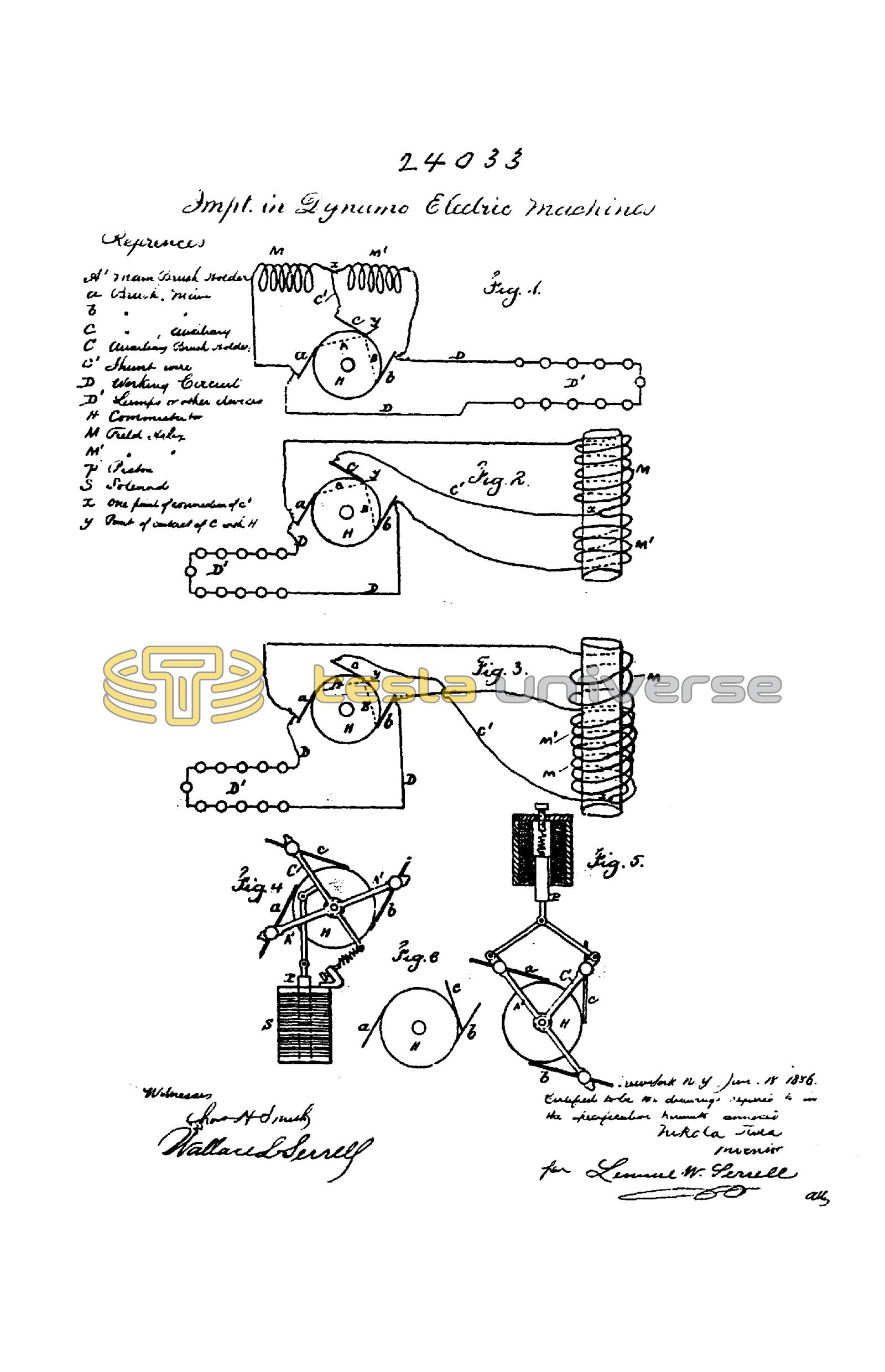
Fig. 1 is a diagram illustrating my invention showing one core of the field magnets with one helix wound in the same direction throughout.
Figs. 2 and 3 are diagrams showing one core of the field magnets with a portion of the helices wound in opposite directions.
Figs. 4 and 5 are diagrams illustrating the electric devices that may be employed for automatically adjusting the brushes and
Fig. 6 is a diagram illustrating the positions of the brushes when the machine is being energised on the start.
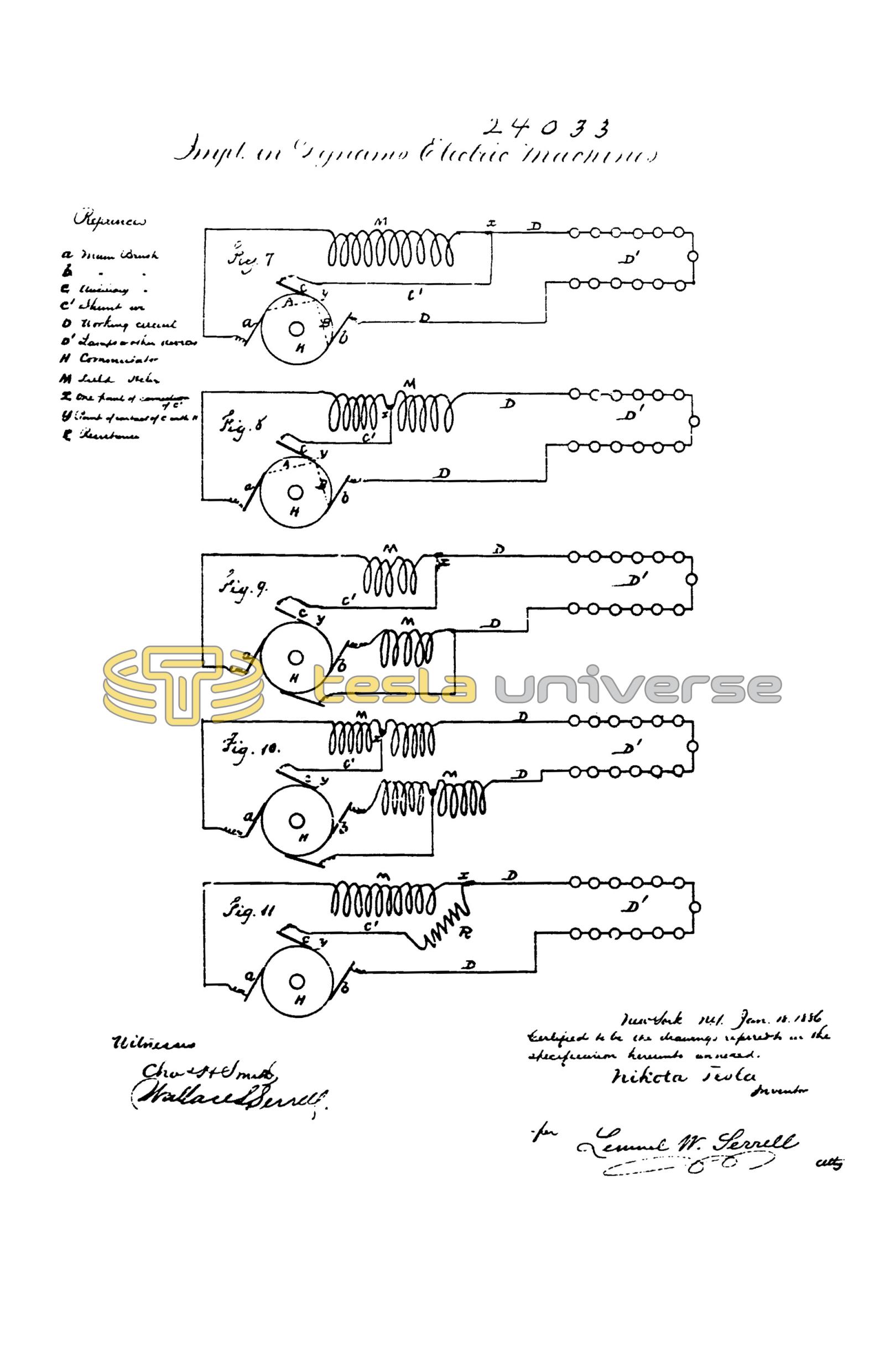
Figs. 7, 3, 9, 10 and 11 are diagrams that further illustrate my invention as hereafter described.
a. and b. are positive and negative brushes of the main or working circuit, and c the auxiliary brush. The working circuit D, extends from the brushes a. and b. as usual and contains electric lamps or other devices D-1 either in series or in multiple arc. M, M-1 represent the field helices, the ends of which are connected to the main brushes a, and b. The branch or shunt wire c-1 extends from the auxiliary brush c, to the circuit of the field helices and is connected to the same at an intermediate point X. H represents the commutator with the plates of ordinary construction.
It is now to be understood that when the auxiliary brush c occupies such a position upon the commutator that the electro-motive force between the brushes c and b as the resistance of the circuit a, M, c-1, c. A. to the resistance of the circuit b, M-1, c-1, c, B. the potentials of the points X and Y will be equal and no current will flow over the auxiliary brush, but when the brush c. occupies a different position, the potentials of the points X and Y will be different and a current will flow over the auxiliary brush to or from the commutator, according to the relative position of the brushes. If for instance the commutator space between the brushes a and c, when the latter is at the neutral point, is diminished, a current will flow from the point Y over the shunt c. to the brush b thus strengthening the current in the part M-1, and partly neutralizing the current in the part M: but if the space between the brushes a and c is increased, the current will flow over the auxiliary brush in an opposite direction and the current in M will be strengthened and in M-1 partly neutralized. By combining with the brushes a, b, and c any known automatic regulating mechanism, the current developed can be regulated in proportion to the demands in the working circuit.
The parts M and M-1 of the field wire may be wound in the same direction, (in this case they are arranged as shown in Fig. 1 or the part M may be wound in the opposite direction as shown in Figs. 2 and 5.)
It will be apparent that the respective cores of the field magnets are subjected to the neutralizing or intensifying effects of the current in the shunt through c-1 and the magnetism of the cores will be partially neutralized or the point of greatest magnetism shifted, so that it will be more or less remote from or approaching to, the armature, and hence the aggregate energizing actions of the field magnets on the armature will be correspondingly varied. In the form indicated in Fig. 1 the regulation is effected by shifting the point of greatest magnetism, and in Figs. 2 and 3 the same effect is produced by the action of the current in the shunt passing through the neutralizing helix.
In Figs. 4 and 5, A-1, A-1, indicate the main brush holder carrying the main brushes, and C, the auxiliary brush holder carrying the auxiliary brush. These brush holders are movable in arcs concentric with the center of the commutator shaft.
An iron piston P of the solenoid S, (Fig. 4) is attached to the auxiliary brush holder C. The adjustment is effected by means of spring and screw or tightened.
In Fig. 5 instead of a solenoid an iron tube enclosing a coil is shown. The piston P of the coil is attached to both brush holders A-1, A-1 and C. When the brushes are moved directly by electrical devices as shown in Figs. 4 and 5 these are so constructed that the force exerted for adjusting is practically uniform through the whole length of motion.
The relative positions of the respective brushes may be varied by moving the auxiliary brush or the brush c may remain quiescent and the core p be connected to the main brush holder A-1 so as to adjust the brushes a, b, in their relation to the brush c. If however an adjustment is applied to all the brushes as seen in Fig. 5 the solenoid should be connected to both A-1 and C so as to move them towards or away from each other. There are several known devices for giving motion in proportion to an electric current. I have shown the moving cores in Figs. 4 and 5, as convenient devices for obtaining the required extent of motion with very slight changes in the current passing through the helices.
It is understood that the adjustment of the main brushes causes variation in the strength of the current independently of the relative position of said brushes to the auxiliary brush. In all cases the adjustment may be such that current flows over the auxiliary brush when the dynamo is running with its normal load.
I am aware that auxiliary brushes have been used in connection with the helices of the field wire, but in these instances the helices received the entire current through the auxiliary brush or brushes and said brushes could not be taken off without breaking the current through the field. These brushes caused however a great sparking upon the commutator. In my improvement the auxiliary brush causes very little or no sparking and can be taken off without breaking the current through the field helices. My improvement has besides the advantage to facilitate the self exciting of the machine in all cases where the resistance of the field wire is very great comparatively to the resistance of the main circuit at the start, for instance on arc-light machines. In this case I place the auxiliary brush c near to or in preference in contact with the brush b, as shown in Fig. 6. In this manner the part M-1, Figs. 1, 2 and 3 is completely cut out, and as the part M has a considerably smaller resistance then the whole length of the field wire the machine excites itself, whereupon the auxiliary brush is shifted automatically to its normal position.
In Figs. 7, 8, 9, 10 and 11 which further illustrate my invention, a. and b. are the positive and negative brushes of the main circuit, and c an auxiliary brush. The main circuit D extends from the brushes a and b, as usual and contains the helices M of the field wire, and the electric lamps or other working devices D-1. The auxiliary brush c is connected to the point x of the main circuit by means of the wire c-1. H is a commutator of ordinary construction. When the electro-motive force between the brushes a and c, is to the electro-motive force between the brushes c and b, as the resistance of the circuit a, M, c-1, c, A, to the resistance of the circuit b, B, c, c-1, D, the potentials of the points x and y, will be equal and no current will pass over the auxiliary brush c, but if said brush occupies a different position relatively to the main brushes, the electric condition is disturbed and current will flow either from y to x, or from x to y, according to the relative position of the brushes. In the first case the current through the field helices will be partly neutralized and the magnetism of the field magnets diminished, in the second case the current will be increased and the magnets will gain strength. By combining with the brushes a, b, c, any automatic regulating mechanism the current developed can be regulated automatically in proportion to the demands in the working circuit. In practice it is sufficient to move only the auxiliary brush as shown in Fig.4 as the regulator is very sensitive to the slightest changes, but the relative position of the auxiliary brush to the main brushes may be varied by moving the main brushes or both main and auxiliary brushes may be moved as illustrated in Fig. 5. In the latter two cases it will be understood the motion of the main brushes relatively to the neutral line of the machine, causes variations in the strength of the current independently of their relative position to the auxiliary brush. In all cases the adjustment may be such that when the machine is running with the ordinary load, no current flows over the auxiliary brush.
The field helices may be connected as shown in Fig. 7 or a part of the field helices may be in the outgoing, and the other part in the return circuit and two auxiliary brushes may be employed as shown in Figs. 9 and 10. Instead of shunting the whole of the field helices a portion only of such helices may be shunted as shown in Fig. 8 and 10.
The arrangement shown in Fig. 10 is advantageous as it diminishes the sparking upon the commutator, the main circuits being closed through the auxiliary brushes at the moment of the break of the circuit at the main brushes.
The field helices may be wound in the same direction or a part may be wound in opposite directions.
The connection between the helices and the auxiliary brush or brushes may be made by a wire of small resistance, or a resistance may be interposed (R. Fig. 11) between the point x and the auxiliary brush or brushes to divide the sensitiveness when the brushes are adjusted.
I claim as my invention:-
1st. The combination with the commutator having two or more main brushes, and an auxiliary brush, of the field helices having their ends connected to the main brushes, and a branch or shunt connection from an intermediate point of the field helices to the auxiliary brush and means for varying the relative position upon the commutator of the respective brushes, substantially as set forth.
2nd. The combination with the commutator, and main brushes and one or more auxiliary brushes, of the field helices in the main circuits and one or more shunt connections from the field helices to the auxiliary brushes, the relative positions upon the commutator, the respective brushes being adjustable for the purpose set forth.
New York NY
Jan. 18. 1886
Nikola Tesla
Signed in the presence of
Chas. H. Smith
Geo. T. Pinckney