Nikola Tesla Patents
Nikola Tesla U.S. Patent 336,962 - Regulator for Dynamo-Electric Machines
NIKOLA TESLA, OF SMILJAN LIKA, AUSTRIA-HUNGARY, ASSIGNOR TO THE TESLA ELECTRIC LIGHT AND MANUFACTURING COMPANY, OF RAHWAY, NEW JERSEY.
REGULATOR FOR DYNAMO-ELECTRIC MACHINES.
SPECIFICATION forming part of Letters Patent No. 336,962 dated March 2, 1886.
Application filed June 1, 1885. Serial No. 167,136. (No model.)
To all whom it may concern:
Be it known that I, NIKOLA TESLA, of Smiljan Lika, border country of Austria-Hungary, have invented an Improvement in Dynamo Electric Machines, of which the following is a specification.
My invention is designed to provide an improved method for regulating the current in dynamo-electric machines.
In another application, No. 165,793, filed by me May 18, 1885, I have shown a method for regulating the current in a dynamo having the field-helices in a shunt. My present application relates to a dynamo having its field-helices connected in the main circuit.
In my improvement I employ one or more auxiliary brushes, by means of which I shunt a portion or the whole of the field-helices. According to the relative position upon the commutator of the respective brushes more or less current is caused to pass through the helices of the field, and the current developed by the machine can be varied at will by varying the relative positions of the brushes.
In the drawings the present invention is illustrated by diagrams, which are hereinafter separately referred to.
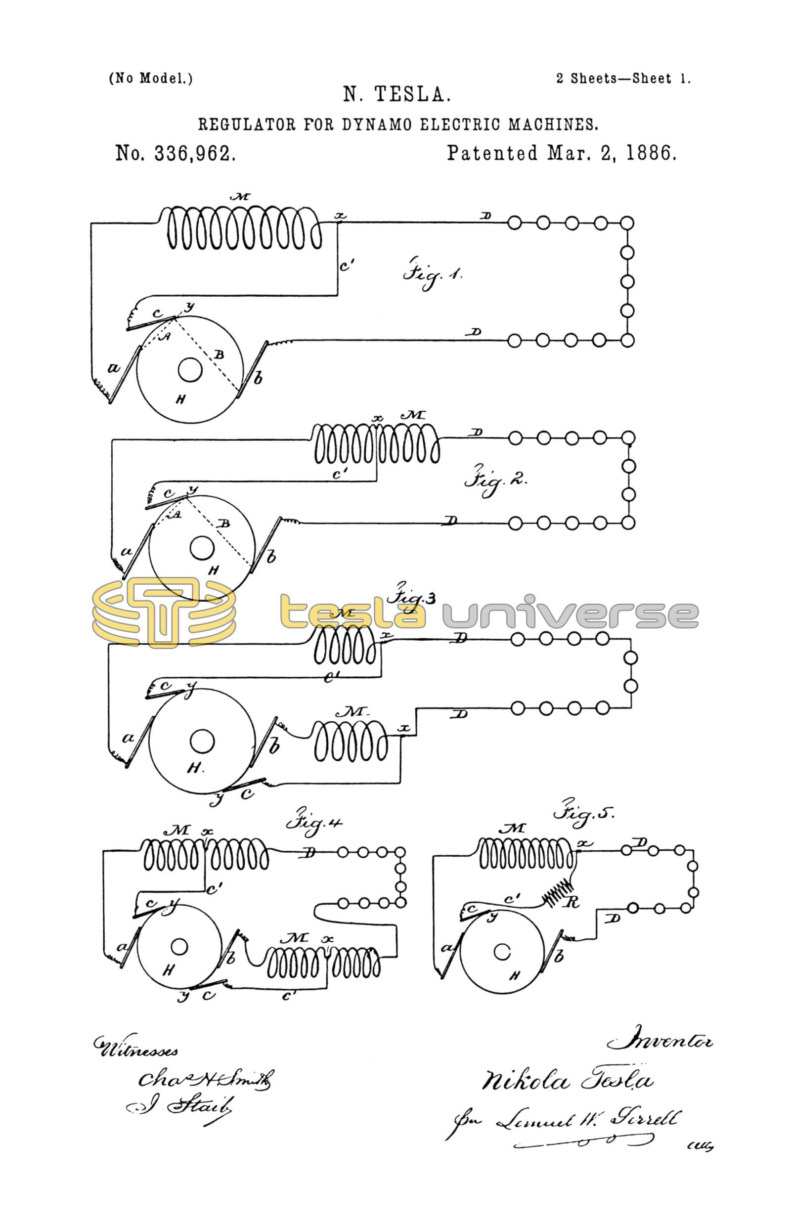
In Figure 1, a and b are the positive and negative brushes of the main circuit, and c an auxiliary brush. The main circuit D extends from the brushes a and b, as usual, and contains the helices M of the field-wire and the electric lamps or other working devices. The auxiliary brush c is connected to the point x of the main circuit by means of the wire c'.
H is a commutator of ordinary construction.
From that which has been said in the application above referred to it will be seen that when the electro-motive force between the brushes a and c is to the electro-motive force between the brushes c and b as the resistance of the circuit a M c' c A to the resistance of the circuit b C B c c' D, the potentials of the points x and y will be equal, and no current will pass over the auxiliary brush c; but if said brush occupies a different position relatively to the main brushes the electric condition is disturbed, and current will flow either from y to x or from x to y, according the the relative position of the brushes. In the first case the current through the field-helices will be partly neutralized and the magnetism of the field-magnets diminished. In the second case the current will be increased and the magnets will gain strength. By combining with the brushes a b c any automatic regulating mechanism the current developed can be regulated automatically in proportion to the demands in the working-circuit.
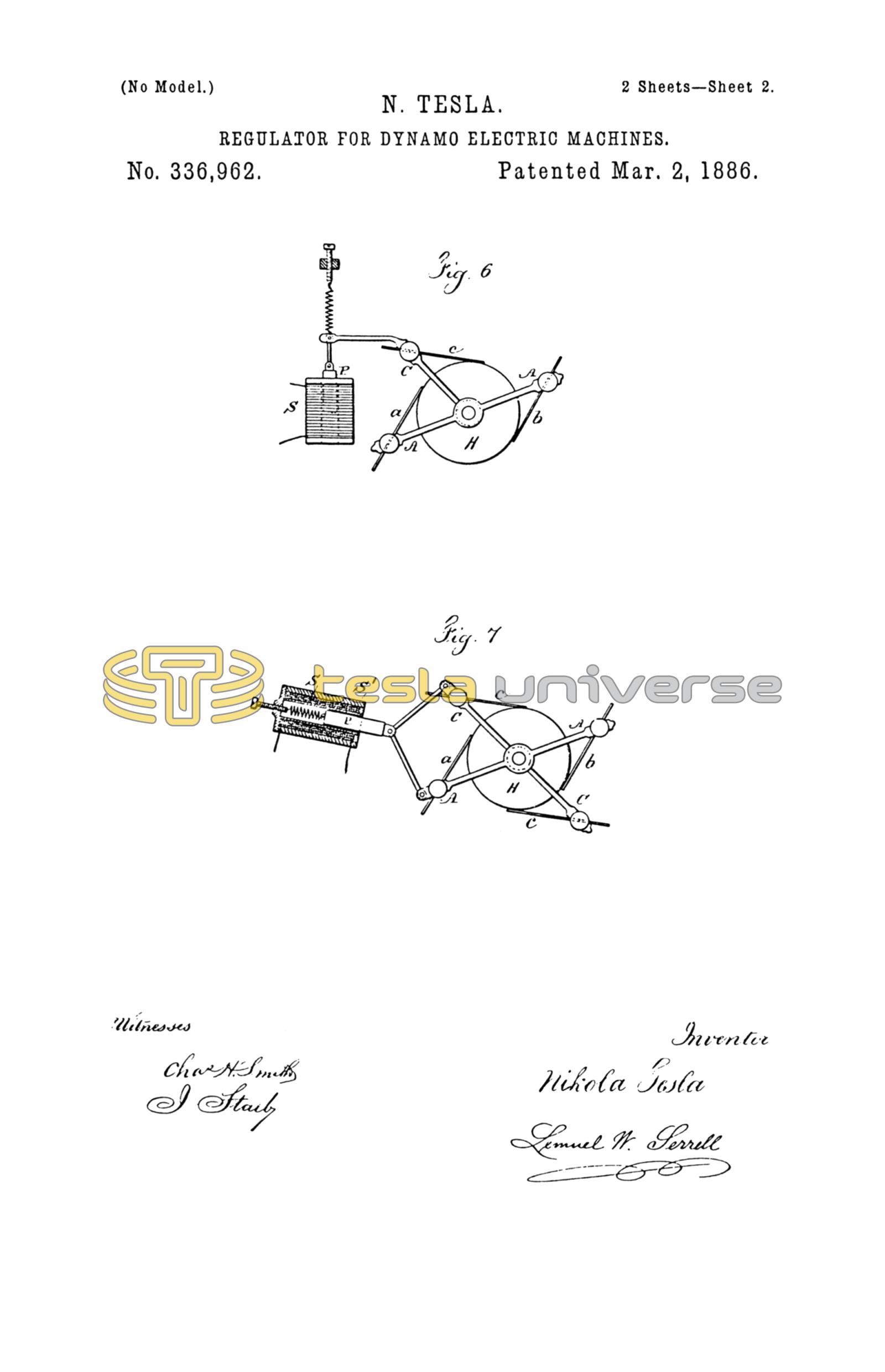
In Figs. 6 and 7 I have represented some of the automatic means that may be used for moving the brushes. The core P, Fig. 6, of the solenoid-helix S, is connected with the brush c to move the same, and in Fig. 7 the core P is shown as within the helix S, and connected with both brushes a and c, so as to move the same toward or from each other, according to the strength of the current in the helix, the helix being within an iron tube, S', that becomes magnetized and increases the action of the solenoid.
In practice it is sufficient to move only the auxiliary brush, as shown in Fig. 6, as the regulation is very sensitive to the slightest changes; but the relative position of the auxiliary brush to the main brushes may be varied by moving the main brushes, or both main and auxiliary brushes may be moved, as illustrated in Fig, 7. In the latter two cases, it will be understood, the motion of the main brushes relatively to the neutral line of the machine causes variations in the strength of the current independently of their relative position to the auxiliary brush. In all cases the adjustment may be such that when the machine is running with the ordinary load no current flows over the auxiliary brush.
The field-helices may be connected as shown in Fig. 1, or a part of the field-helices may be in the outgoing and the other part in the return circuit, and two auxiliary brushes may be employed as shown in Figs. 3 and 4. Instead of shunting the whole of the field-helices, a portion only of such helices may be shunted, as shown in Figs. 2 and 4.
The arrangement shown in Fig. 4 is advantageous, as it diminishes the sparking upon the commutator, the main circuit being closed through the auxiliary brushes at the moment of the break of the circuit at the main brushes. The field-helices may be wound in the same direction, or part may be wound in opposite directions.
The connection between the helices and the auxiliary brush or brushes may be made by a wire of small resistance, or a resistance may be interposed (R, Fig. 5) between the point x and the auxiliary brush or brushes to divide the sensitiveness when the brushes are adjusted.
I am aware that it is not new to use auxiliary brushes on the commutator, and that auxiliary brushes have been connected to the field-helices; but I am not aware that the helices of a series dynamo have been shunted by means of auxiliary brushes, and that the relative position of the respective brushes has been varied for the purpose of regulating the current developed by the machine.
In instances where auxiliary brushes have been used in connection with the field-helices said auxiliary brushes received the current continuously and caused great sparking, whereas in my invention the auxiliary brush receives current only when the normal electrical conditions of the circuit are disturbed.
I claim as my invention—
The combination, with the commutator and main brushes and one or more auxiliary brushes, of the field-helices in the main circuits and one or more shunt-connections from the field-helices to the auxiliary brushes, the relative positions upon the commutator of the respective brushes being adjustable, for the purpose set forth.
Signed by me this 16th day of May, A.D. 1885.
NIKOLA TESLA.
GEO. T. PINCKNEY,
WALLACE L. SERRELL.