Nikola Tesla Patents
Nikola Tesla U.S. Patent 396,121 - Thermo-Magnetic Motor
NIKOLA TESLA, OF SMILJAN, LIKA, AUSTRIA-HUNGARY.
THERMO-MAGNETIC MOTOR.
SPECIFICATION forming part of Letters Patent No. 396,121, dated January 15, 1889.
Application filed March 30, 1886. Serial No. 197,115. (No model.)
To all whom it may concern:
Be it known that I, NIKOLA TESLA, of Smiljan, Lika, border country of Austria-Hungary, have invented an Improvement in Thermo-Magnetic Motors, of which the following is a specification.
It is well known that heat applied to a magnetized body will lessen the magnetism, and if the temperature is raised sufficiently the magnetism will be neutralized or destroyed.
In my present invention I obtain mechanical power by a reciprocating action resulting from the joint operations of heat, magnetism, and a spring or weight or other force—that is to say, I subject a body magnetized by induction or otherwise to the action of heat until the magnetism is sufficiently neutralized to allow a weight or spring to give motion to the body and lessen the action of the heat, so that the magnetism may be sufficiently restored to move the body in the opposite direction, and again subject the same to the demagnetizing of the heat.
In carrying out my invention I am able to make use of either an electro-magnet or a permanent magnet, and I preferably direct the heat against a body that is magnetized by induction, rather than directly against a permanent magnet, thereby avoiding the loss of magnetism that might result in the permanent magnet by the action of heat. I also provide for lessening the volume of the heat or for intercepting the same during that portion of the reciprocation in which the cooling action takes place.
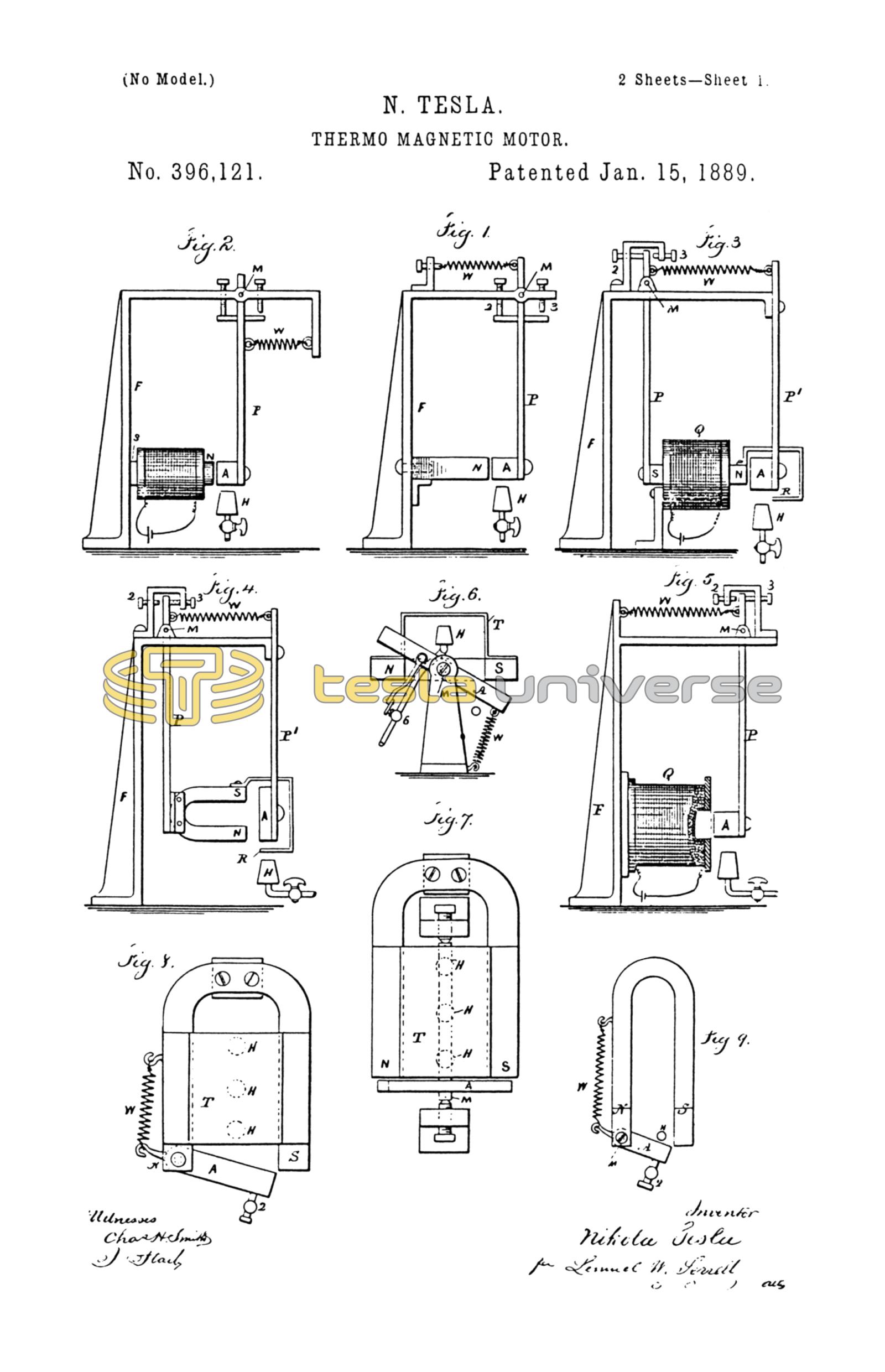
In the drawings I have represented by diagrams some of the numerous arrangements that may be made use of in carrying out my invention. In all of these figures the magnet-poles are marked N S, the armature A, the Bunsen burner or other source of heat H, the axis of motion M, and the spring or the equivalent thereof—namely, a weight—is marked W.
In Figure 1 the permanent magnet N is connected with a frame, F, supporting the axis M, from which the arm P hangs, and at the lower end of which the armature A is supported. The stops 2 and 3 limit the extent of motion, and the spring W tends to draw the armature A away from the magnet N. It is now to be understood that the magnetism of N is sufficient to overcome the spring W and draw the armature A toward the magnet N. The heat acting upon the armature A neutralizes its induced magnetism sufficiently for the spring W to draw the armature A away from the magnet N and also from the heat at H. The armature now cools and the attraction of the magnet N overcomes the spring W and draws the armature A back again above the burner H, so that the same is again heated and the operations are repeated. The reciprocating movements thus obtained are employed as a source of mechanical power in any desired manner. Usually a connecting-rod to a crank upon a fly-wheel shaft will be made use of, as indicated in Fig. 10; but I do not limit myself in this respect.
Fig. 2 represents the same parts as before described; but an electro-magnet is illustrated in place of a permanent magnet. The operations, however, are the same.
In Fig. 3 I have shown the same parts as in Figs. 1 and 2, only they are differently arranged. The armature A, instead of swinging, is stationary and held by an arm, P', and the core N S of the electro-magnet is made to swing within the helix Q, the said core being suspended by the arm P from the pivot M. A shield, R, is connected with the magnet-core and swings therewith, so that after the heat has demagnetized the armature A to such an extent that the spring W draws the core N S away from the armature A the shield R comes between the flame H and armature A, thereby intercepting the action of the heat and allowing the armature to cool, so that the magnetism, again preponderating, causes the movement of the core N S toward the armature A and the removal of the shield R from above the flame, so that the heat again acts to lessen or neutralize the magnetism. A rotary or other movement may be obtained from this reciprocation.
Fig. 4 corresponds in every respect with Fig. 3, except that a permanent horseshoe-magnet, N S, is represented as taking the place of the electro-magnet in said Fig. 3.
In Fig. 5 I have shown a helix, Q, with an armature adapted to swing toward or from the helix. In this case there may be a soft-iron core in the helix, or the armature may assume the form of a solenoid-core, there being no permanent core within the helix.
Fig. 6 is an end view, and Fig. 7 a plan view, illustrating my improvement as applied to a swinging armature, A, and a stationary permanent magnet, N S. In this instance I apply the heat to an auxiliary armature or keeper, T, which is adjacent to and preferably in direct contact with the magnet. This armature T, in the form of a plate of sheet-iron, extends across from one pole to the other and is of sufficient section to practically form a keeper for the magnet, so that when this armature T is cool nearly all the lines of force pass over the same and very little free magnetism is exhibited. Then the armature A, which swings freely on the pivots M in front of the poles N S, is very little attracted and the spring s pulls the same away from the poles into the position indicated in the drawings. The heat is directed upon the iron plate T at some distance from the magnet, so as to allow the magnet to be kept comparatively cool. This heat is applied beneath the plate by means of the burners H, and there is a connection from the armature A or its pivot to the gas-cock 6 or other device for regulating the heat. The heat acting upon the middle portion of the plate T, the magnetic conductivity of the heated portion is diminished or destroyed, and a great number of the lines of force are deflected over the armature A, which is now powerfully attracted and drawn into line, or nearly so, with the poles N S. In so doing the cock 6 is nearly closed and the plate T cools, the lines of force are again deflected over the same, the attraction exerted upon the armature A is diminished, and the spring W pulls the same away from the magnet into the position shown by full lines, and the operations are repeated. The arrangement shown in Fig. 6 has the advantages that the magnet and armature are kept cool and the strength of the permanent magnet is better preserved, as the magnetic circuit is constantly closed.
In the plan view, Fig. 8, I have shown a permanent magnet and keeper-plate, T, similar to those in Figs. 6 and 7, with the burners H for the gas beneath the same; but the armature is pivoted at one end to one pole of the magnet and the other end swings toward and from the other pole of the magnet. The spring W acts against a lever-arm that projects from the armature, and the supply of heat has to be partly cut off by a connection to the swinging armature, so as to lessen the heat acting upon the keeper-plate when the armature A has been attracted.
Fig. 9 is similar to Fig. 8, except that the keeper T is not made use of and the armature itself swings into and out of the range of the intense action of the heat from the burner H.
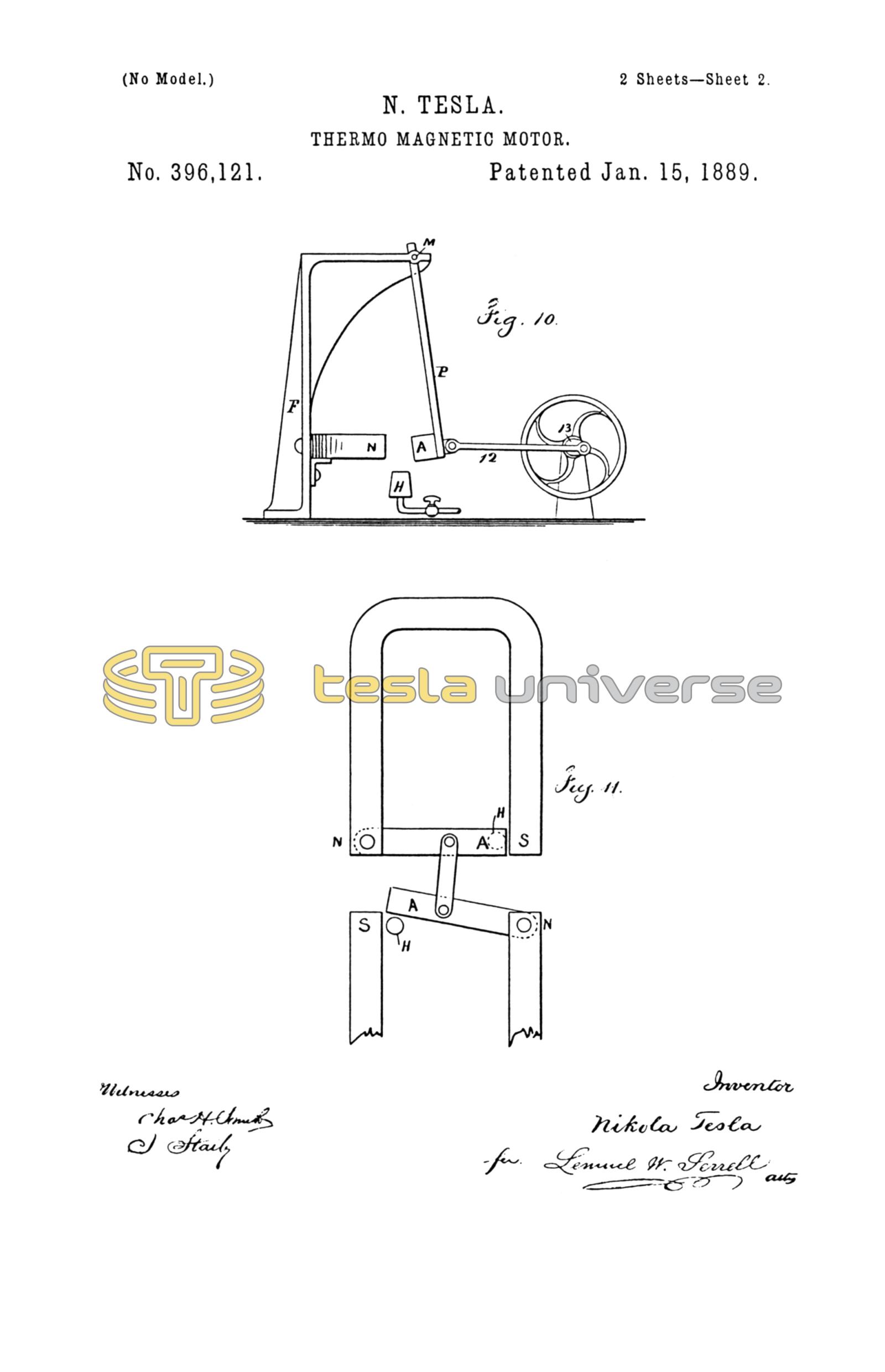
Fig. 10 is a diagram similar to Fig. 1, except that in place of using a spring and stops the armature is shown as connected by a link, 12, to the crank 13 of a fly-wheel, so that the fly-wheel will be revolved as rapidly as the armature can be heated and cooled to the necessary extent. A spring may be used in addition, as in Fig. 1.
In Fig. 11 the two armatures A A are connected by a link, so that one will be heating while the other is cooling, and the attraction exerted to move the cooled armature is availed of to draw away the heated armature instead of using a spring.
I have shown in the drawings several ways of carrying out my invention; but said invention is not limited by any particular form, arrangement, or construction of devices.
I claim as my invention—
1. The combination, with a swinging body under the influence of magnetism, of a burner or other source of heat acting to vary the magnetism, and a spring or other power to move the swinging body in the opposite direction to the action of the magnetism, substantially as set forth.
2. The combination, with two or more armatures connected to each other, of magnets to influence such armatures, and burners or other sources of heat to vary the magnetic action and cause the armatures to move, substantially as set forth.
Signed by me this 29th day of March, 1886.
NIKOLA TESLA.
GEO. T. PINCKNEY,
WALLACE L. SERRELL.