Nikola Tesla Patents
Nikola Tesla U.S. Patent 609,248 - Electric Circuit Controller
NIKOLA TESLA, OF NEW YORK, N. Y.
ELECTRIC-CIRCUIT CONTROLLER.
SPECIFICATION forming part of Letters Patent No. 609,248, dated August 16, 1898.
Application filed March 12, 1898. Serial No. 673,559. (No model.)
To all whom it may concern:
Be it known that I, NIKOLA TESLA, of the borough of Manhattan, in the city, county, and State of New York, have invented certain new and useful Improvements in Circuit-Controllers, of which the following is a specification, reference being had to the drawings accompanying and forming a part of the same.
In previous applications filed by me, notably in Serial No. 660,518, filed December 2, 1897, and others, I have shown and described various forms of electric-circuit controllers in which a conducting fluid is used for one or both of the terminals. These contrivances, while applicable generally as a means of making and breaking an electric circuit with great rapidity, were devised by me more especially for use in my now well-known system of electrical conversion by means of condenser-discharges and for this reason have been designed with especial reference to the peculiar and exceptional conditions which obtain in such systems. My present invention is an improvement in circuit-controllers of this kind, and in order that the object and nature of the improvement may be more readily understood and appreciated I may refer briefly to the more essential characteristics of the devices described before upon which the present improvement is based. As it was primarily essential that these controllers be capable of making and breaking the circuit at very rapid rate and as such a result could not be secured practically or economically by any of the ordinary devices employing rigid contacts or terminals I was led to invent apparatus in which the circuit connections were established and broken between a rigid terminal and a fluid conductor or between two fluid conductors in the form of jets or streams. In the forms of apparatus employing a rigid or solid conductor as one terminal and a fluid as the other the makes and breaks of course occur always between a solid and a fluid terminal, and although the operative parts of my improved circuit-controllers were usually confined in air or gas tight receptacles and in an inert medium, both for the purpose of improving their action and preventing deterioration of the terminals, there is still a liability to wear of the rigid or solid terminal.
Under certain conditions, as when the circuit-controller is operated from a source of direct current, the deterioration of the solid terminal may be materially reduced by connecting it to the negative pole of the generator. Nevertheless, there will be always a slow wearing away of the metal, which to overcome entirely in a novel manner is the object of my present improvement. To do this, I effect the closure of the circuit through two parts of conducting fluid; but instead of breaking the circuit by the movement of these two parts or terminals, as before, I separate them periodically by the interposition of an insulator which is preferably solid and refractory. For example, I provide a plate or disk with teeth or projections—preferably of glass, lava, or the like—which are caused by the rotation of the disk to pass through the fluid conductor, jet, or whatever it may be, and thus effect a make and break of the circuit.
By means of such a device the breaks always occur between fluid terminals, and hence the deterioration and consequent impairment of the qualities of the apparatus are avoided.
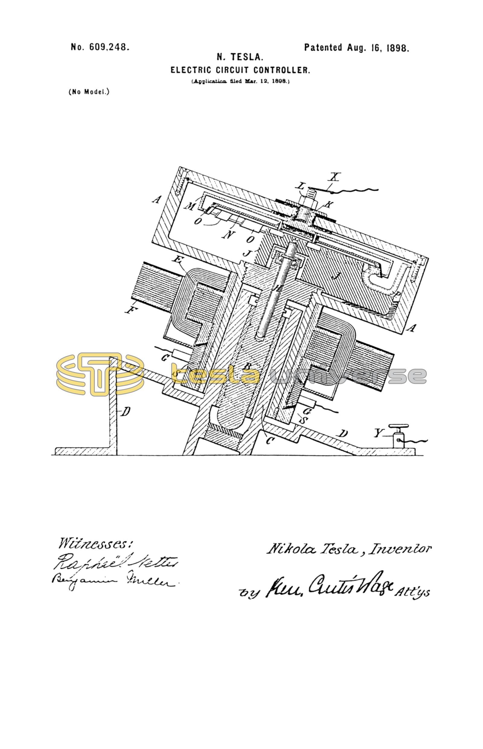
A preferred form of my improved circuit-controller is illustrated in the accompanying drawing, which shows a central vertical section of the same.
The two terminals are contained in an air-tight receptacle A, of iron or steel, which is mounted on a spindle B in a suitable socket or support C, so as to rotate freely. The socket C is secured to or forms part of a base or stand D. Any suitable means may be employed for effecting the rotation of the receptacle, and in illustration of a convenient and practicable means for this purpose I have shown an armature E, secured to a cylindrical extension of the receptacle that surrounds the socket C, and a field-magnet F, which is supported independently and is stationary. The armature-coils are connected with the segments S of a commutator on which bear brushes G.
In the spindle B and concentric with its axis is a spindle H, supported on ball-bearings or otherwise arranged to have a free movement of rotation relatively to the spindle B, so as to be as little as possible influenced by the rotation of the latter.
Any convenient means is provided to oppose or prevent the rotation of the spindle H during the rotation of the receptacle. In the particular arrangement here shown for this purpose a weight or weighted arm J is secured to the spindle H and eccentrically to the axis of the latter, and as the bearing for the spindle B holds the same at an angle to the vertical this weight acts by gravity to hold the spindle H stationary.
Secured to the top or cover of the receptacle A by a stud K, which passes through an insulating-bushing in said cover and is held by a nut L, is a circular disk M, of conducting material, preferably iron or steel, having its edge turned downwardly and then inwardly to provide a peripheral trough on the under side of the disk.
To the under side of the disk M is secured a second disk N, having downwardly-enclosed peripheral projections O O, of insulating and preferably refractory material, in a circle concentric with the disk M.
A tube or duct P is mounted on the spindle H or the weight J and is so arranged that the orifice at one end is directed outwardly toward the trough of the disk M, while the other lies close to the inner peripheral wall of the receptacle, so that if a quantity of mercury or other conducting fluid be placed in the receptacle and the latter rotated the tube or duct P, being held stationary, will take up the fluid which is carried by centrifugal action up the side of the receptacle and deliver it in a stream or jet against the trough or flange of the disk M or against the inner surfaces of the projections O of disk N, as the case may be.
Obviously, since the two disks M and N rotate with respect to the jet or stream of fluid issuing from the duct P, the electrical connection between the receptacle and the disk M through the fluid will be completed by the jet when the latter passes to the disk M between the projections O and will be interrupted whenever the jet is intercepted by the said projections.
The rapidity and the relative duration of the makes and breaks is determined by the speed of rotation of the receptacle and the number and width of the intercepting projections O.
By forming that portion of the disk M with which the jet makes contact as a trough, which will retain when in rotation a portion of the fluid directed against it, a very useful feature is secured. The fluid under the action of centrifugal force accumulates in and is distributed along the trough and forms a layer over the surface upon which the jet impinges. By this means a very perfect contact is always secured and all deterioration of the terminal surfaces avoided.
The principle of interrupting the circuit by intermittently passing an insulator through a fluid conductor may be carried out by many specifically-different forms of apparatus, and in this respect I do not limit myself to the particular form herein shown.
What I claim is—
1. In an electrical-circuit controller, the combination with a conductor forming one of the terminals, of means for maintaining a jet or stream of conducting fluid forming the other terminal, and directing it against said conductor, and a body adapted to be intermittently moved through and to intercept the jet or stream, as set forth.
2. In an electrical-circuit controller, the combination with a rigid terminal, of means for directing against such terminal a jet or stream of conducting fluid in electrical connection with the other terminal, and a body adapted to be intermittently moved through and to intercept the jet or stream, as set forth.
3. In. an electrical-circuit controller, the combination with a rigid terminal, of means for directing against such terminal a jet or stream of conducting fluid in electrical connection with the other terminal, a body having a series of radial projections and means for rotating the same so that the said projections will intermittently intercept the stream or jet, as set forth.
4. In a circuit-controller, the combination with a rotary conductor forming one terminal, means for directing against such terminal a jet or stream of conducting fluid in electrical connection with the other terminal, and a body with spaced projections mounted to rotate in a path that intercepts the jet or stream of fluid, as set forth.
5. In a circuit-controller, the combination with a rotary conductor forming one terminal, and means for directing intermittently against such terminal a jet or stream of fluid in electrical connection with the other terminal, the part of said rotary conductor upon which the jet or stream impinges being formed so as to retain, by centrifugal force, a portion of the fluid directed against it, as set forth.
6. The combination of the receptacle, the conducting-disk secured within it, the insulated disk with peripheral projections and the stationary tube or duct for directing a stream or jet of conducting fluid toward the conducting-disk and across the path of the projections O, as set forth.
7. The combination of the receptacle, the conducting-disk with a peripheral trough-shaped flange, the insulated disk with peripheral projections O, and the stationary tube or duct for directing a stream or jet of conducting fluid into the trough-shaped flange of the conducting-disk and across the path of the projections O, as set forth.
NIKOLA TESLA.
M. LAWSON DYER,
G. W. MARTLING.