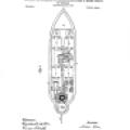
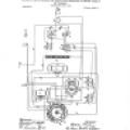
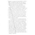
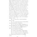
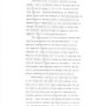
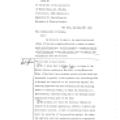
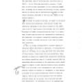
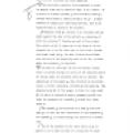
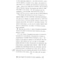
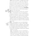
No. 613,809. Patented Nov. 8, 1898. N. TESLA. METHOD OF AND APPARATUS FOR CONTROLLING MECHANISM OF MOVING VESSELS OR VEHICLES. (Application filed July 1, 1898.) (No Model.) Fig.1 Witnesses: Raphaël
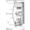
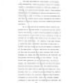
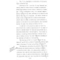
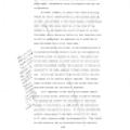
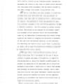
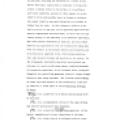
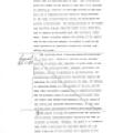
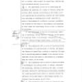
218 No. 613,809. Patented Nov. 8, 1898. N. TESLA. METHOD OF AND APPARATUS FOR CONTROLLING MECHANISM OF MOVING VESSELS OR VEHICLES. (Application Aled July 1, 1898) (No Model.) T. Fig.2 Witnesses
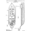
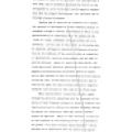
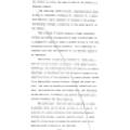
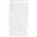
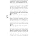
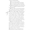
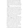
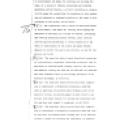
No. 613,809. Patented Nov. 8, 1898. N. TESLA. METHOD OF AND APPARATUS FOR CONTROLLING MECHANISM OF MOVING VESSELS OR VEHICLES. (Application Aled July 1, 1898) (No Model.) Fig.3 TITITE T 0. 134
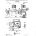
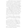
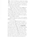
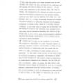
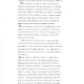
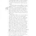
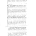
220 No. 613,809. Patented Nov. 8, 1898. .N. TESLA. METHOD OF AND APPARATUS FOR CONTROLLING MECHANISM OF MOVING VESSELS OR VEHICLES. (Application filed July 1, 1898.) (No Model.) Fig.4 Fig.5 www
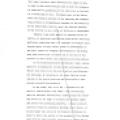
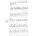
No. 613,809. Patented Nov. 8, 1898. N. TESLA. METHOD OF AND APPARATUS FOR CONTROLLING MECHANISM OF MOVING VESSELS OR VEHICLES. (Application filed July 1, 1998.) (No Model.) Fig.10 Witnesses: Raphail
15.98 613809 Nikola Tesla Patent No. New York, County of PAR State of New York... Invention Mechod of apparatus for Contealing the Mechanism of Moving Vessels or Vehicles. July 1, 1898. Fast a
224 State of New York, County of New York. - ot Nikola Tesla, the above-named petitioner, being duly sworn, deposes and says that he is a citizen of the United States, and resident of New York City
T T Sub., bus. speen. Sept. 20/98 To all whom it may concern: Be it known that 1, Nikola Tesla, a citizen of the United States, residing at New York, in the County and State of New York, have invented
226 movement of the same with the desired rapidity, by the necèssity for effecting the control from a point which is practically fixed, and by many well-understood drawbacks inseparably connected with
The many and difficult requirements of the object here contemplated, involving peculiar means for transmitting to a considerable distance an influence capable of causing, in a positive and reliable
228 the effective range of the influence thus extended over a vast area, and by carefully adjusting the circuit on the moving body so as to be in exact electro-magnetic synchronism with the primary
T J that under otherwise equal conditions the length of wire be half of that which would be used if both the terminals be connected or, generally, if the circuit be in the form of a closed loop or
230 the greatest practicable distance, thus extending the range and usefulness of my invention. A great variety of electrical and other devices, more or less suitable for the purpose of detecting and
Again, another contrivance capable of being utilized in detecting feeble electrical effects, consists of two conducting plates or terminals which have preferably wires of some length attached to them
232 ment is in many cases unnecessary for the successful carrying out of my invention, I nevertheless make it a rule to bestow upon this feature the greatest possible care, not only because of the
It should be stated before, in regard to the sensitive devices above mentioned, which may be broadly considered as belonging to one class --ina smuch as the operation of all of them involves the
234 astrous consequences and such cases, in which the sure and timely working of the machinery is of paramount importance, may often present themselves in practice, and this consideration has
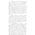
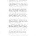
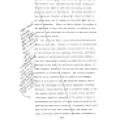
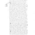
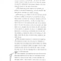
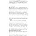
Fig. 9 is a diagrammatic illustration of the system in its preferred form. Referring to fig. 1 and fig. 2, A may designate any type of vessel or vehicle which is capable of being propelled and
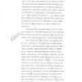
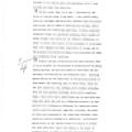
236 the circuit is either the same as that of the source or a harmonic thereof. The receiving circuit proper, diagrammatically shown in fig. 3, comprises a terminal E', conductor C¹, a sensi! tive
A metallic strip d', secured to an insulated post d", bears against the side of the cylinder c, connecting it with one part of the circuit. The central rod c" is connected to the frame of the
238 Two pins i', i' extend out from the lever h", and one of these being always in the path of a projection on arm e, they operate to prevent the turning of cylinder c with the spindle h and the
1 gas or atmosphere in which the particles are immersed and to certain deficiencies, well known to experts, of the transmitting apparatus as heretofore employed, which are in a large measure reduced
240 action. To insure the retraction of its armature e after the current has been established through the magnet I and interrupted by the inversion of the sensitive device A, a light rod k is
K' K", fig. 1 and fig. 3, are two relay magnets, conveniently placed in the rear of the propelling engine. One terminal of a battery k" is connected to one end of each of the relay.coils; the opposite
242 The outer circle of contacts comprises two long plates, 7 and 8, on opposite sides of the disk, and a series of shorter plates, 9, 10, 11, 12, 13 and 14 in the front and rear. Flexible conductors
) otto ever the position of the rudder is less than a predetermined angle, conveniently forty-five degrees from the centhe ston cicuit . ter position. In order, however, to prevent the rudder from
244 devide devide strong varying currents. In addition to the mechanism described the vessel may carry any other devices or apparatus as might be required for accomplishing any special object of more
T lights. Both of the lights may be colored, and by flashing them up whenever desired, the operator may guide the vess el in its course. For such purposes also the standards rr are provided, which
246 Appt Prousel persenta description of the operatio sture artrit arrested on points tt, that is, to the right or left of the operator, he is reminded that the vessel is being deflected to the right
Cauc Kject all method cls. attack, nor could an armour or protection of any kind be built to resist the charge which it might carry. But by reason of its unlimited destructiveness it will afford a
248 controlling circuit, adjusted or rerd ered sensitive to waves or disturbances of a definite character, establishing a region of such waves or disturbances, and rendering by their means the
1 J T subject to Cristian 9. The combination with a source of electrical waves. incomplete; or disturbances, and means for starting and stopping the operation of the same, of a vessel or vehicle
250 Room No. 85.... A communications should be addressed to "The Commissioner of Patents, Washington, D. C." Nikola Tesla, % Kerr, Curtis & Page, 120 Broadway, 2-071 a. DEPARTMENT OF THE INTERIOR
884,934,--2. stated in the specification how a luminaus discharge night be utilized to control a set of devices such as propelling and steering mechanisms. On pages 11 and 16, the receiving circuit is
252 684,934,--3. manipulations of the devices T are necessary to start, stop and reverse the motor D as well as to control the motor 7. The matter beginning with line 19 on page 23 of the
JEJ (J 13 13 000 63 (31JDJDJDUDDDD 884,934,--4, Clain 10 is rejected for the reason that it does not comply with the requirements of the statutes and Rules of Practice (see Section 4888 of Revised
254 Serb. Speicin Room 85. In the matter of the application. of Nikola Tesla, No. 684,934, filed July 1, 1898, Method of & Apparatus for Controlling the Movements of Floating Vessels. New York
ODLUGOUDUDLILILI UJ CILJUJU ject, such as a boat, or any floating vessel, whereby the movements and course of such body or vessel may be directed and controlled fram a distance, and any device carried
256 all of those systems which provide for the control of the mechanism carried by a moving object and governing its motion, in that I require no intermediate wires, cables or other form of electrical
31313 CICL3 63 63DDCDD 63 13 L) LI In this case the action at a given distance will be the stronger the larger the area enclosed by the conductor and the greater the rate of change of the current. If
258 3 time be the same, the circuit should now have a length of conductor only one half of that used in the former case. Still another way is to pass the currents simply through the ground by
T 4 limited to the special mode and appliances which I have devised and shall here describe. In any event, that is to say -- whichever of the above or similar plans I may adopt -- and, particularly
260 When an electrical disturbance reaches a circuit so arranged and adjusted, additional strain is put upon the insulating film which gives way and allows the passage of a current, which can be
} } J J 5 PI It will be obviously noted from the preceding that, whichever of these or similar contrivances be used, the sensitiveness and, what is often still more important, the reliability of
262 the same body, each of which may have a distinct duty to fulfil. In the following description, however, I shall show a still further development in this direction namely how, by making use of
an official, directing the movements of a vessel in the man ner described, should find it necessary to bring into action a special device on the latter, or to perform a particular operation, perhaps
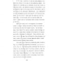
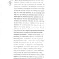
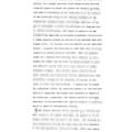
264 tion of the controlling mechanism. Fig. 5 is an end view of the same. Fig. 6 shows the same mechanism in side elevation. (Fig. 7 is a side view of a detail of the mechanism. Fig. 8 is a central
} bearings at the stem of the boat and carrying the rudder 3¹. Pin The apparatus, by means of which the operation of both the propelling and steering mechanisms is controlled, involves, primarily, a
266 and a current traverses the relay magnet a. The particular sensitive device employed is shown in general views and in detail in Figs. 4, 6, 7 and 8. It consists of a metal cylinder c with
J T J T quarter revolution of spindle ¹. The end of the former spindle extends through the side of the frame and carries an eccentric cylinder h' which passes through a slot in a lever h" pivoted to
268 many causes as, the une qual size, weight and shape of the grains, the unequal pressure which results from this and from the manner in which the grains are usually agitated, the lack of uniformity
J To tion of the relay, to precisely the same electrical condition, and offer the same resistance to the flow of the battery current until another impulse from afar reaches. the receiving circuit. O
270 -17always in connection with plate i', the other always in connection with the plate i", and the third adapted to rest on the strips i and in succession or upon the intermediate insulating spaces
71 circles of conducting contact plates. Brushes 1, 2, 3 and 4 bear upon the inner circle of contacts, while the brushes 5 and 6 bear upon the outer circle of contacts. The The outer circle of
272 Crasid Oct. 5-1898 battery. Hence the motor F may always be caused to rotate in one direction, whatever may be the position of the rudder, and may be caused to rotate in either direction whenever
3 J 12 may affect the sensitive device. It is this consideration chiefly, which makes it advisable to use the two relays K' K" which otherwise might be dispensed with. They should be also placed as
274 73 to the insulating segment 23. But since the head L carrying the segments is geared to the rudder, the position of the latter is in a general way determined by observing the lights. Both of the
twice, once to right and once to left. Now I preferably place the handle of the switch so that when it is arrested on points tt', that is, to the right or left of the operator, he is reminded that the
276 rear of the circle. Under these conditions the rudder will be turned to starboard, and the circuit of motor D interrupted between brushes 5 and 6. At the same time, only one of the circuits of
) J 74 ed direction, when the handle T is turned to the point u. This produces another action of the relay a and brush J' is shifted onto insulation and both relays K and K" are inactive. to The
278 P As previously explained, the longest period of operation of which the motor F is capable under ordinary conditions of use does not permit the motor m to shift the arm m' into contact with the
J ? Erased Clet. 4.1 4.1/98) sal or vehicle, which control the propelling, steering and other mechanism therean, as set forth. F The improvement in the art of controlling the movements and operation
280 767 or disturbances and means for starting and stopping the same, of a vessel or vehicle, propelling and steering mechanism carried thereby, a circuit containing or connected with means for
mag net in circuit with the material, and an escapement controlled by said magnet and adapted to permit a half revolution of the receptacle when the said magnet is energizedas set forth. $12 15. The
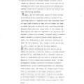
282 The fact that vessels have been controlled by electric currents directed from a stationary source through metallic conductors is fully recognized. The further fact that a receiving apparatus, more
movements through the natural media of space would have been regarded as a pure chimera, as a flight of fancy, which had no place in the useful arts. When such a suggestion, however, is accompanied by
284 not been done before by any method. We file herewith an additional sheet of drawing, as required by the office. We respectfully request a reconsideration of the application as now amended. -31Rec
A Room 85. In the matter of the application of NIKOLA TESLA, No.684, 934, Filed July 1,1898, Method of and Apparatus for Controlling the Movements of Vessels. Washington, D.C. Oct. 4th, 1898. Hon
286 Cancelclaim 5. This claim is canceled for the reason that it is thought to be objectionable on the score of form rather than substance Ken. Center Mage Alles In Zedda.
Room 85. In the matter of the application of Nikola Tesla, No. 684,934, filed July 1, 1898. Method of and Apparatus for Controlling the Movements of Floating Vessels. Hon. Commissioner of Patents: ---