Plans
An Adjustable Tesla Coil
Every so often there appears an article on how to make a Tesla coil, of approved construction. Not one of the many articles which the writer has seen to date has described a coil which is in the least adjustable, consequently the secondary voltage must be regulated directly from the primary of the high tension transformer, by regulating the voltage supplied, either by resistance or by means of an adjustable choke coil. Both methods are very wasteful of the current.
The writer has the coil described herewith in operation on a 1½ K. W. transformer and same is easily controllable, directly from the Tesla Coil primary. The output from such a coil may be varied within large limits.
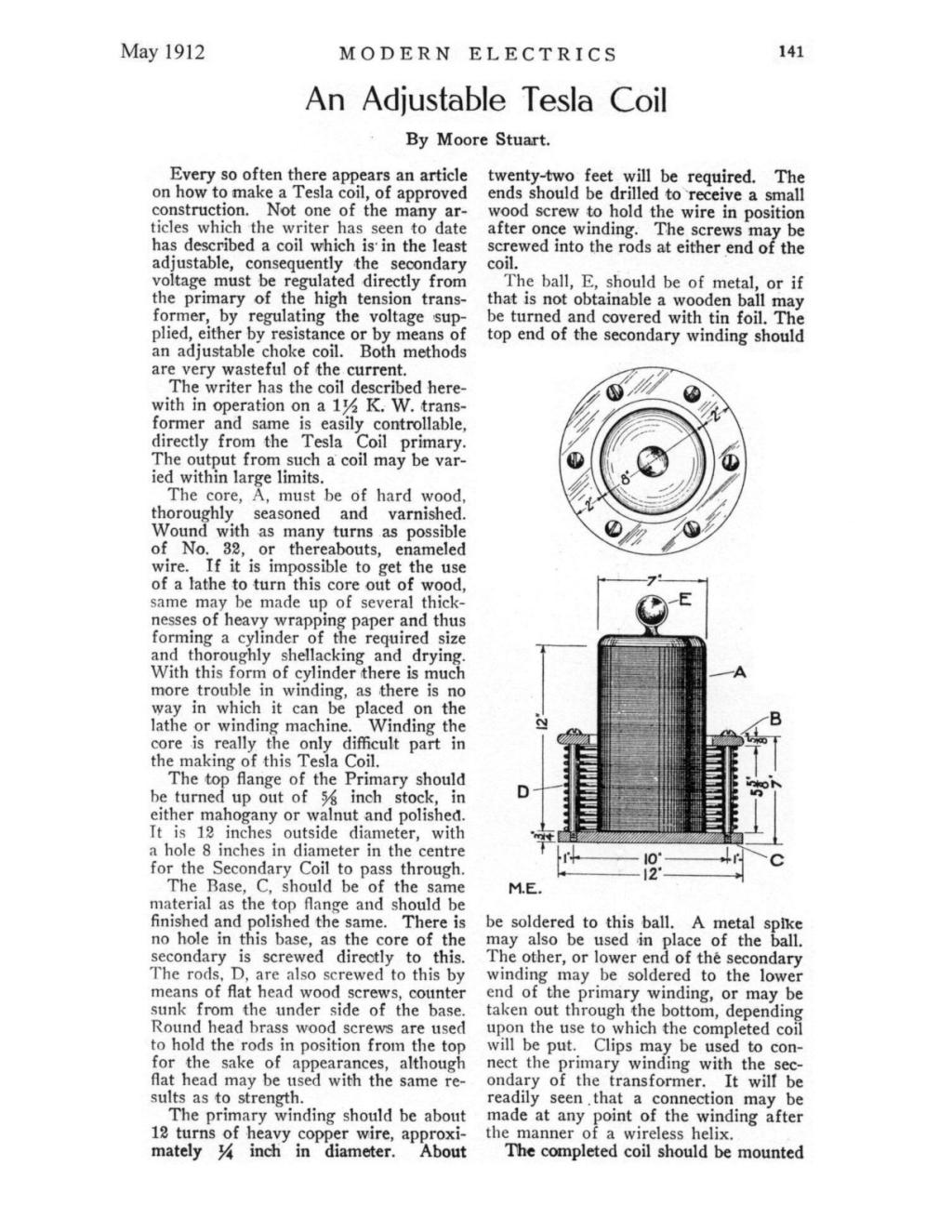
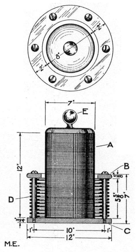
The core, A, must be of hard wood, thoroughly seasoned and varnished. Wound with as many turns as possible of No. 32, or thereabouts, enameled wire. If it is impossible to get the use of a lathe to turn this core out of wood, same may be made up of several thicknesses of heavy wrapping paper and thus forming a cylinder of the required size and thoroughly shellacking and drying. With this form of cylinder there is much more trouble in winding, as there is no way in which it can be placed on the lathe or winding machine. Winding the core is really the only difficult part in the making of this Tesla Coil.
The top flange of the Primary should be turned up out of ⅝ inch stock, in either mahogany or walnut and polished. It is 12 inches outside diameter, with a hole 8 inches in diameter in the centre for the Secondary Coil to pass through.
The Base, C, should be of the same material as the top flange and should be finished and polished the same. There is no hole in this base, as the core of the secondary is screwed directly to this. The rods, D, are also screwed to this by means of flat head wood screws, counter sunk from the under side of the base. Round head brass wood screws are used to hold the rods in position from the top for the sake of appearances, although flat head may be used with the same results as to strength.
The primary winding should be about 12 turns of heavy copper wire, approximately ¼ inch in diameter. About twenty-two feet will be required. The ends should be drilled to receive a small wood screw to hold the wire in position after once winding. The screws may be screwed into the rods at either end of the coil.
The ball, E, should be of metal, or if that is not obtainable a wooden ball may be turned and covered with tin foil. The top end of the secondary winding should be soldered to this ball. A metal spike may also be used in place of the ball. The other, or lower end of the secondary winding may be soldered to the lower end of the primary winding, or may be taken out through the bottom, depending upon the use to which the completed coil will be put. Clips may be used to connect the primary winding with the secondary of the transformer. It will be readily seen that a connection may be made at any point of the winding after the manner of a wireless helix.
The completed coil should be mounted on four insulators to insulate it from the earth.
This coil may be adapted to be used for wireless telephonic purposes by merely placing a slider upon the secondary for the adjustment of same. It will be readily understood that this winding should not be adjusted while working the coil, especially if used for wireless purposes with a large condenser, as the number of oscillations per second will be so low as to be dangerous to human life.
If used as a Tesla Coil, many weird and interesting experiments may be carried out. If used with a small condenser on a 1 K. W. transformer, with the entire circuit in resonance, an 8 inch spark may easily be drawn to the hand, if a small piece of metal is held in the hand, without any sensation whatever. However, it is not well to try and receive the current from such a coil unless one is experienced in the action and use of such apparatus, as there are so many factors to be considered, before the current from the secondary is not dangerous to life. Even though the voltage from such a coil be enormous, it will be remembered that but 250 milliamperes or ¼ ampere is generally conceded to be enough to destroy the heart action of a man in average condition, and sometimes very much less current will have the same destructive effect.