Nikola Tesla Patents
Nikola Tesla U.S. Patent 685,012 - Means for Increasing the Intensity of Electrical Oscillations
NIKOLA TESLA, OF NEW YORK, N. Y.
MEANS FOR INCREASING THE INTENSITY OF ELECTRICAL OSCILLATIONS.
SPECIFICATION forming part of Letters Patent No. 685,012, dated October 22, 1901.
Application filed March 21, 1900. Renewed July 3, 1901. Serial No. 66,980. (No model.)
To all whom it may concern:
Be it known that I, NIKOLA TESLA, a citizen of the United States, residing at the borough of Manhattan, in the city, county, and State of New York, have invented certain new and useful Improvements in Means for Increasing the Intensity of Electrical Oscillations, of which the following is a specification, reference being had to the drawings accompanying and forming part of the same.
In many scientific and practical uses of electrical impulses or oscillations—as, for example, in systems of transmitting intelligence to distant points—it is of great importance to intensify as much as possible the current impulses or vibrations which are produced in the circuits of the transmitting and receiving instruments, particularly of the latter.
It is well known that when electrical impulses are impressed upon a circuit adapted to oscillate freely the intensity of the oscillations developed in the same is dependent on the magnitude of its physical constants and the relation of the periods of the impressed and of the free oscillations. For the attainment of the best result it is necessary that the periods of the impressed should be the same as that of the free oscillations, under which conditions the intensity of the latter is greatest and chiefly dependent on the inductance and resistance of the circuit, being directly proportionate to the former and inversely to the latter. In order, therefore, to intensify the impulses or oscillations excited in the circuit—in other words, to produce the greatest rise of current or electrical pressure in the same—it is desirable to make its inductance as large and its resistance as small as practicable. Having this end in view I have devised and used conductors of special forms and of relatively very large cross-section; but I have found that limitations exist in regard to the increase of the inductance as well as to the diminution of the resistance. This will be understood when it is borne in mind that the resonant rise of current or pressure in a freely-oscillating circuit is proportionate to the frequency of the impulses and that a large inductance in general involves a slow vibration. On the other hand, an increase of the section of the conductor with the object of reducing its resistance is, beyond a certain limit, of little or no value, principally because electrical oscillations, particularly those of high frequency, pass mainly through the superficial conducting layers, and while it is true that this drawback may be overcome in a measure by the employment of thin ribbons, tubes, or stranded cables, yet in practice other disadvantages arise, which often more than offset the gain.
It is a well-established fact that as the temperature of a metallic conductor rises its electrical resistance increases, and in recognition of this constructors of commercial electrical apparatus have heretofore resorted to many expedients for preventing the coils and other parts of the same from becoming heated when in use, but merely with a view to economizing energy and reducing the cost of construction and operation of the apparatus.
Now I have discovered that when a circuit adapted to vibrate freely is maintained at a low temperature the oscillations excited in the same are to an extraordinary degree magnified and prolonged, and I am thus enabled to produce many valuable results which have heretofore been wholly impracticable.
Briefly stated, then, my invention consists in producing a great increase in the intensity and duration of the oscillations excited in a freely-vibrating or resonating circuit by maintaining the same at a low temperature.
Ordinarily in commercial apparatus such provision is made only with the object of preventing wasteful heating, and in any event its influence upon the intensity of the oscillations is very slight and practically negligible, for as a rule impulses of arbitrary frequency are impressed upon a circuit, irrespective of its own free vibrations, and a resonant rise is expressly avoided.
My invention, it will be understood, does not primarily contemplate the saving of energy, but aims at the attainment of a distinctly novel and valuable result—that is, the increase to the greatest practicable degree of the intensity and duration of free oscillations. It may be usefully applied in all cases when this special object is sought, but offers exceptional advantages in those instances in which the freely-oscillating discharges of a condenser are utilized.
The best and most convenient manner of carrying out the invention of which I am now aware is to surround the freely-vibrating circuit or conductor, which is to be maintained at a low temperature, with a suitable cooling medium, which may be any kind of freezing mixture or agent, such as liquid air, and in order to derive the fullest benefit from the improvement the circuit should be primarily constructed so as to have the greatest possible self-induction and the smallest practicable resistance, and other rules of construction which are now recognized should be observed. For example, when in a system of transmission of energy for any purpose through the natural media the transmitting and receiving conductors are connected to earth and to an insulated terminal, respectively, the lengths of these conductors should be one-quarter of the wave length of the disturbance propagated through them.
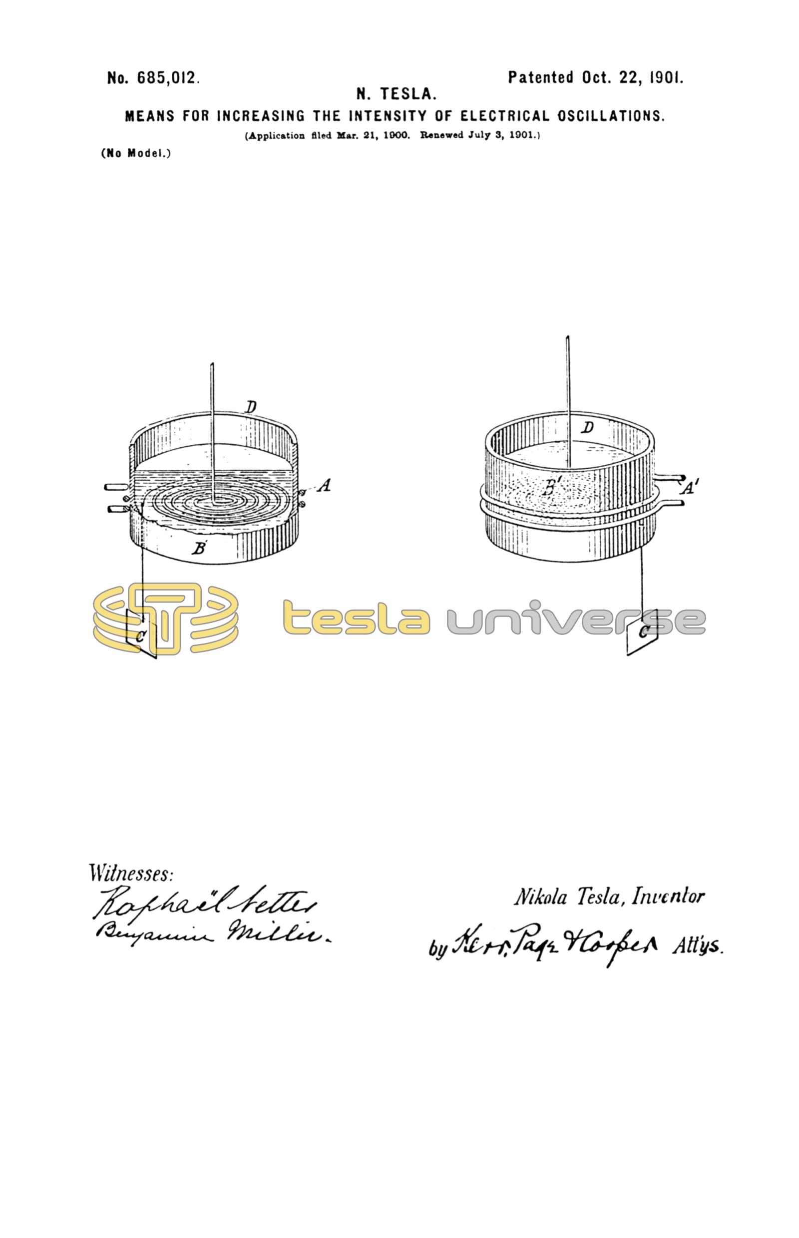
In the accompanying drawing I have shown graphically a disposition of apparatus which may be used in applying practically my invention.
The drawing illustrates in perspective two devices, either of which may be the transmitter, while the other is the receiver. In each there is a coil of few turns and low resistance, (designated in one by A and in the other by A'.) The former coil, supposed to be forming part of the transmitter, is to be connected with a suitable source of current, while the latter is to be included in circuit with a receiving device. In inductive relation to said coils in each instrument is a flat spirally-wound coil B or B', one terminal of which is shown as connected to a ground-plate C, while the other, leading from the center, is adapted to be connected to an insulated terminal, which is generally maintained at an elevation in the air. The coils B B' are placed in insulating-receptacles D, which contain the freezing agent and around which the coils A and A' are wound.
Coils in the form of a flat spiral, such as those described, are eminently suited for the production of free oscillations; but obviously conductors or circuits of any other form may be used, if desired.
From the foregoing the operation of the apparatus will now be readily understood. Assume, first, as the simplest case that upon the coil A of the transmitter impulses or oscillations of an arbitrary frequency and irrespective of its own free vibrations are impressed. Corresponding oscillations will then be induced in the circuit B, which, being constructed and adjusted, as before indicated, so as to vibrate at the same rate, will greatly magnify them, the increase being directly proportionate to the product of the frequency of the oscillations and the inductance of circuit B and inversely to the resistance of the latter. Other conditions remaining the same, the intensity of the oscillations in the resonating-circuit B will be increased in the same proportion as its resistance is reduced. Very often, however, the conditions may be such that the gain sought is not realized directly by diminishing the resistance of the circuit. In such cases the skilled expert who applies the invention will turn to advantage the reduction of resistance by using a correspondingly longer conductor, thus securing a much greater self-induction, and under all circumstances he will determine the dimensions of the circuit, so as to get the greatest value of the ratio of its inductance to its resistance, which determines the intensity of the free oscillations. The vibrations of coil B, greatly strengthened, spread to a distance and on reaching the tuned receiving-conductor B' excite corresponding oscillations in the same, which for similar reasons are intensified, with the result of inducing correspondingly stronger currents or oscillations in circuit A', including the receiving device. When, as may be the case in the transmission of intelligible signals, the circuit A is periodically closed and opened, the effect upon the receiver is heightened in the manner above described not only because the impulses in the coils B and B' are strengthened, but also on account of their persistence through a longer interval of time. The advantages offered by the invention are still more fully realized when the circuit A of the transmitter instead of having impulses of an arbitrary frequency impressed upon it is itself permitted to vibrate at its own rate, and more particularly so if it be energized by the freely-oscillating high-frequency discharges of a condenser. In such a case the cooling of the conductor A, which may be effected in any suitable manner, results in an extraordinary magnification of the oscillation in the resonating-circuit B, which I attribute to the increased intensity as well as greater number of the high-frequency oscillations obtained in the circuit A. The receiving-coil B' is energized stronger in proportion and induces currents of greater intensity in the circuit A'. It is evident from the above that the greater the number of the freely-vibrating circuits which alternately receive and transmit energy from one to another the greater, relatively, will be the gain secured by applying my invention.
I do not of course intend to limit myself to the specific manner and means described of artificial cooling, nor to the particular forms and arrangements of the circuits shown. By taking advantage of the facts above pointed out and of the means described I have found it possible to secure a rise of electrical pressure in an excited circuit very many times greater than has heretofore been obtainable, and this result makes it practicable, among other things, to greatly extend the distance of transmission of signals and to exclude much more effectively interference with the same than has been possible heretofore.
Having now described my invention, what I claim is—
1. The combination with a circuit adapted to vibrate freely, of means for artificially cooling the same to a low temperature, as herein set forth.
2. In an apparatus for transmitting or receiving electrical impulses or oscillations, the combination with a primary and a secondary circuit, adapted to vibrate freely in response to the impressed oscillations, of means for artificially cooling the same to a low temperature, as herein set forth.
3. In a system for the transmission of electrical energy, a circuit upon which electrical oscillations are impressed, and which is adapted to vibrate freely, in combination with a receptacle containing an artificial refrigerant in which said circuit is immersed, as herein set forth.
4. The means of increasing the intensity of the electrical impulses or oscillations impressed upon a freely-vibrating circuit, consisting of an artificial refrigerant combined with and applied to such circuit and adapted to maintain the same at a low temperature.
5. The means of intensifying and prolonging the electrical oscillations produced in a freely-vibrating circuit, consisting of an artificial refrigerant applied to such circuit and adapted to maintain the same at a uniformly low temperature.
6. In a system for the transmission of energy, a series of transmitting and receiving circuits adapted to vibrate freely, in combination with means for artificially maintaining the same at a low temperature, as set forth.
NIKOLA TESLA.
JOHN C. KERR,
M. LAWSON DYER.