Nikola Tesla Books
Books written by or about Nikola Tesla

Related content from pages
Designation
347
Designation
349

upon the extra coil as the wires of the oscillator proper, wound on the wooden structure seen in the back behind the coil, are short-circuited. One of the terminals of the condensers is grounded so that when they are discharging through the circuit, chiefly composed of a number of turns of the regulating coil, there is a strong vibration propagated through the ground which through the ground wire w reaches the “extra coil”. Now, generally, the energy which can thus be transmitted to the coil would be minute, but when the oscillations passing through the ground are exactly of the frequency of the “extra coil” system itself, a considerable current passes into the coil which then acts just as a hole would in a pipe through which a fluid is pumped by means of a pulsating piston. As the magnifying factor of the coil is very large the feeble impulses reaching the ground wire and lamps magnify the impressed e.m.f. and create considerable movement of electricity through the lamps which are thus brilliantly lighted, as shown in the photograph. In the experiment the capacity in the exciting oscillating circuit, impressing the vibrations upon the ground and wire w, was 3 tanks on each side or 1 1/2 tanks total, that is 54 bottles or 0.0009 x 54 = 0.0486 mfd, approx. The total inductance was 41,000 cm + ind. Of 6 1/4 turns of regulating coil = 41,000 + 19,368 = 60,000 cm, approx. or 0.00006 henry. From this the approximate period of the vibration impressed upon the ground would be
Tp = $! {{2 \pi \over 10^{3}} \sqrt{0.0486 \times {6 \over 10^{5}}}} $! = $! {{2 \pi \over 10^{5}} \sqrt{0.02916}} $! = $! {{2 \pi \over 10^{5}} \times 0.1708} $! = $! {1.074 \over 10^{5}} $!
approx. and n = 93,110 and p = 585,000 approx. λ would be very nearly 2 miles and $! {λ \over 4} $! = 1/2 mile or about 2640 feet. In reality the length of the wire in the excited system - that is extra coil and ground wire, was found by measurement to be 2660 feet (98 turns, wire No. 6, 25' 11" each turn = 2540' + 3/4 turn of cable inside of secondary frame = 112' + continuation of ground cable outside of circle to ground plate = 28' + wire w = 20' + rubber covered wire on top of coil = 50' that is, total 2450' + 112' + 28' + 20' + 50' =2660 feet. From above data and taking resistance of extra coil at 1 ohm (in reality a little less) we get magnifying factor for coil alone $! {p L \over R} $! = $! {{585,000 \times 0.018} \over 1} $! = 10,530.
Taking, however, into consideration that the resistance of the lamps was about 1000 ohms roughly, when including the latter in the system the factor would be only about $! {1 \over 1000} $! of this, or approximately only 10.5. But I believe that the resistance of the lamps when operated by currents of such extreme frequencies is much smaller than the measured resistance according to the usual methods. The currents, namely, when produced in such ways as these here employed, have very high maximum values and the carbon is brought periodically to a much higher temperature than when operated with steady currents or currents of ordinary frequencies. I have observed this repeatedly. Furthermore when such currents as these here are used some part of the discharge also passes through
Designation
350
the rarefied gas in the bulb and there is a corresponding diminution of the effective resistance of the lamp on this account. In fact, I think that it is chiefly owing to this that the resistance becomes very small, it being a fact that such currents pass with the greatest freedom through the rarefied gas particularly when it is maintained at a high temperature, as in the case here considered. The heating of the gas has the effect of increasing the incandescence of the carbon and it is well demonstrated that an incandescent lamp takes, for a given luminosity, less energy when operated with currents of such extreme frequencies. Owing to these reasons the magnifying factor of the excited system even with the lamps included must have been very much larger than the figure last mentioned. It was astonishing to note, in the experiment recorded on the plate, how much energy can be in this manner conveyed to such a carefully synchronized coil through the ground. The supply transformers were cut down by a regulating coil in the primary to less than one half, in fact to about 1/3 of full capacity and inasmuch as only 3 tanks on each side in the primary or exciting circuit were used while 8 tanks were available, it is evident that, if the excited system would have been designed to work with full output of the exciting apparatus it would have been quite practicable to light, say 3 x 8/3 = 8 times as many lamps, or about 40 lamps. However, inasmuch as the five lamps were far above candle power it would have been, in all probability, possible to light 60 lamps or so to normal candle power by a specially designed coil, with a liberal allowance of copper, vibrating in unison with the system exciting the portion of the ground containing the ground plate. Nothing could convey a better idea of the tremendous activity of this apparatus and a simple comparison with well ascertained data, obtained with other induction apparatus, shows that one of the problems followed up here, that is the establishment of communication with any point of the globe irrespective of distance, is very near its practical solution. The existence of stationary waves proves the feasibility of the project almost beyond any doubt. The great amount of energy which can be conveyed to such a synchronized circuit, by conduction through the ground, makes it appear possible, that the necessity of elevating terminals in my system of energy transmission to a distance may be dispensed with in many instances and that, with a very moderate elevation of, say, a few hundred feet enough energy may be conveyed to a circuit to serve for one or another useful purpose beyond mere signalling, or such uses of the system in which a minute amount of energy is required. Certainly, the amount of energy conveyed in this manner was, in some experiments with this apparatus, surprising at first. An interesting consideration in this connection may be the following: As before stated the period of the exciting or primary circuit, when resonance with the extra coil was attained, was Tp = $! {{2 \pi \over 10^{3}} \sqrt{0.0486 \times {6 \over 10^{5}}}} $!. Now the period of the excited system was Ts = $! {{2 \pi \over 10^{3}} \sqrt{0.018 \times C_{s}}} $!, in which Cs is the “ideal” capacity as designated in previous instances, that is the capacity which would have to be joined to the free end of the “extra coil” of inductance of 0.018 henry but devoid of all distributed capacity. Since Tp = Ts we find Cs = $! {{0.0486 \times {6 \over 10^{5}}} \over 0.018} $! mfd, or
Cs = $! {{9 \times 10^{5} \times 0.0486 \times {6 \over 10^{5}}} \over 0.018} $! = $! {{54 \times 0.0486} \over 0.018} $! = $! {{54 \times 486} \over 180} $! = $! {{3 \times 486} \over 10} $! = 145.8 cm.
Designation
351
Suppose an ideal system of this kind excited in the manner described, so that capacity on the free end is charged each time as the current alternates to a potential P. Then, since as before stated, the system in experiment illustrated was vibrating about 93,000 times per second, the total energy set in movement in the system would be
2 x 93,000 x $! {{P^{2} \times 145.8} \over {2 \times 9 \times 10^{11}}} $! watts.
Let it be further assumed that 1% of the total energy set in movement is frittered down in the lamps and that the number of these were 60, as might have been the case in the presently described experiment. Suppose each lamp to take 50 watts, the total energy consumed in the lamps would be 3000 watts hence, under the above assumptions, the total energy set in movement in the excited system would have to be 100 times this amount or 300,000 watts. To satisfy this condition we would have
2 x 93,000 x $! {{P^{2} \times 145.8} \over {2 \times 9 \times 10^{11}}} $! = 300,000
and
P2 = $! {{54 \times 10^{13}} \over {186 \times 145.8}} $! = $! {10^{12} \times {540 \over {186 \times 145.8}}} $! or P = $! {10^{6} \sqrt{540 \over {186 \times 145.8}}} $! =
= $! {10^{6} \sqrt{540 \over 27,118.8}} $! = $! {10^{6} \sqrt{0.02}} $! approx. or = $! {10^{6} \sqrt{2 \over 100}} $! = $! {10^{5} \sqrt{2}} $! =
= 105 x 1.414 or P = 141,400 volts.
Not very much, as will be seen, for such a pressure is extremely small with apparatus of the kind used here. Taking P roughly as 140,000 volts and assuming that the ground plate be at such a distance that only 1000 volts are impressed upon the same then the magnifying factor would have to be only 140. Of course, this is merely an example to support the above statement that considerable energy may in this way, and by such apparatus, be conveyed to a distant circuit which is connected to the ground at only one point directly or, if desired, through a condenser.

Related content from annotations
The explanation to Photograph XXII concerning the transmission of power from the excited primary circuit to the “extra coil” via the earth is similar to that he gave in 1893(6). The experiment to which the photograph refers was made with the aim of estimating the power of the oscillator from the thermal effect of the HF current. What Tesla calls the “total energy set in movement” would correspond to the total energy transferred to condenser in the secondary (i.e. the power) if an energy of $!{1 \over 2}$! CV2 is transferred in each half-cycle. It can be shown that the active power dissipated in the circuit is much less than this and is inversely proportional to the Q-factor of the oscillating circuit.
6
Tesla: “On light and other high frequency phenomena”, a lecture delivered before the Franklin Ins. Philadelphia, Febr. 1893, L-107.
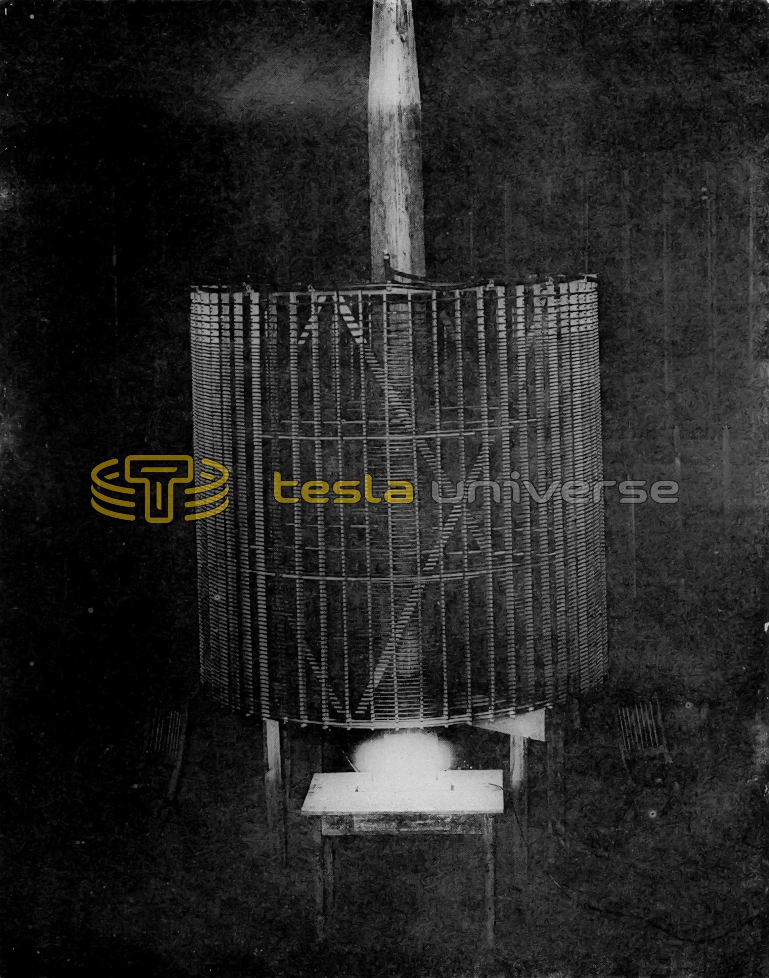
Phot. XXII. Five incandescent lamps lighted by current passing from "extra coil" to ground plate.