TCBA Volume 8 - Issue 1
Page 15 of 18
Tesla Air-Friction Speed Indicator
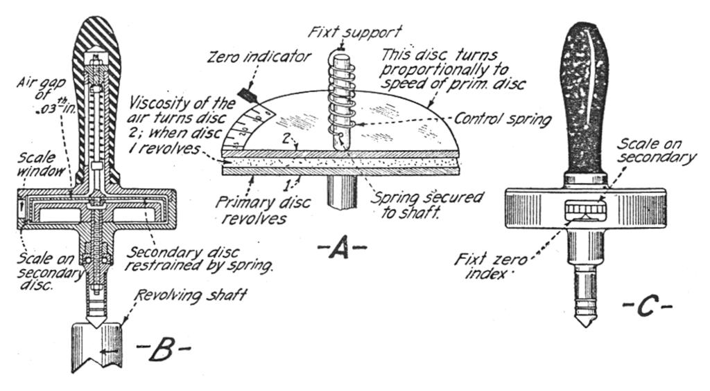
One of the latest wonders of applied science perhaps is the new Tesla speed indicator put out by the well known Waltham watch concern. Contrary to all previous designs and schemes employed in producing a direct-reading speed indicator or tachometer, as the engineers call it, Dr. Nikola Tesla, the famous electrical and radio expert, has here shown us a new trick in the physics of gases and liquids.
As becomes clear from the accompanying illustrations, this direct-reading speed indicator is supplied and calibrated to read in revolutions per minute, or in miles per hour, et cetera, according to the use to which the instrument is to be put; there is no direct mechanical connection between the driving and driven members of the instrument. In a few words what happens is this: When the first cup or disk secured to the driving spindle is rapidly rotated, by having its pointed end placed in contact with the engine- or motor-shaft for example, the thin layer of air, about .03" thick, between it and the secondary disk or cup acts by virtue of its viscosity or friction to drag around the secondary disk, which carries a dial from which the speed is read off by means of a fixt zero index or pointer.
In a later patent Dr. Tesla covers a scheme for using mercury instead of air between the cups or disks, in order to give a more pronounced and reliable scale reading or deflection of the pivoted secondary member, when the instrument is to be calibrated for low speeds. One of the remarkable outstanding features of the new Tesla speed indicator is the fact that the scale divisions are all of equal size, thus making the instrument much easier to read and also much simpler in its calibration. In calibrating, it is simply necessary to adjust the correcting or biasing spring, until the needle just reaches the upper part of the dial when the upper limit of speed to which the instrument is to be adapted is reached; it is then a simple matter to divide up the scale into equal divisions and to evaluate each division or group of divisions. The action of the apparatus is almost uncanny to the uninitiated, but the fact that the instrument has now been brought out commercially proves that it will do the work claimed for it, and that Dr. Tesla's theory and ideas as explained in his patents covering the device are correct.
A comprehensive laboratory test has proved that air friction is not influenced by heat, cold, or changes in altitude up to 10,000 feet. The makers of this instrument, which is being fitted on many of the leading high grade American motor cars this season, further state that by using this Tesla principle, a uniform scale of calibration is possible without oscillation or swinging of the needle, and the instrument further indicates immediately any speed-change.
End
Condenser Tester and Capacity Meter
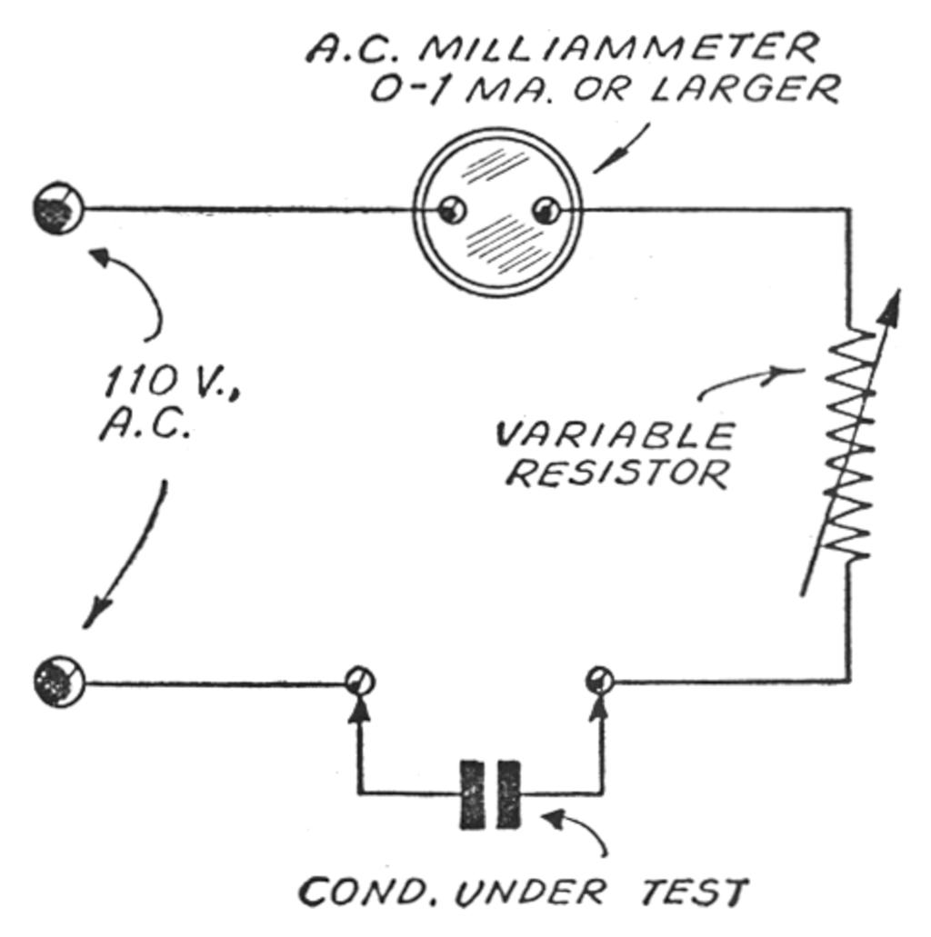
Here is a condenser tester and capacity meter which I constructed with a few parts at low cost and which works very well. As shown in the diagram, it consists of a small A.C. milliammeter and a variable resistor, also a source of current. These, with the condenser which is to be tested, are all connected in series and the meter measures the amount of current which apparently “flows through” the condenser. Since a large condenser passes a greater amount of current than a smaller one, the larger readings of capacity will be near the full scale end of the meter scale. The scale can be calibrated in mfs. by using some reliable make of condenser for calibration purposes, and then the meter can be used as a direct-reading capacity meter. The resistor is used to obtain a “zero-adjustment” on the meter. Since the circuit is essentially a series circuit, with the condenser test leads shorted a full scale reading should be obtained. An open condenser (shorted condenser) will give a full scale reading while a good condenser will give a reading proportionate to its capacity.
This meter cannot be used to test electrolytic condensers, since they are polarized, and cannot be connected into an alternating current circuit without ruining them. - Louis Castelli.


