TCBA Volume 8 - Issue 1
Page 17 of 18
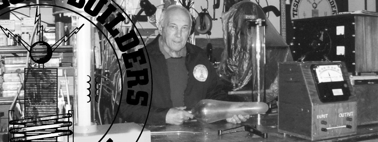
A Home Constructed Shocking Machine
By
Ed Kagle
When people come to my home, they never fail to inquire about the strange contraptions (Tesla coils) in my workshop. Of course, it always pleases me to see them quickly exiting the door as soon as the 4' discharges start lapping at their heals. Sometimes I feel cheated because my guests are gone before I can show them some of the other goodies. One of the projects that never fails to create fun and entertainment is a home constructed shocking machine. The inspiration for building this device goes back to the days when just about every tobacco shop or variety store had a shocking machine on the counter. All you had to do was to drop a penny into the slot and grab onto the two knobs - YEOW!
The basics for my shocking machine are shown in the diagrams that follow. They are shown here not so much to be duplicated but to act as a guide as well as to activate your own talents and ingenuity. How you build it will depend upon the contents of your scrap parts box and what you can scrounge up at the local electronics or surplus shop. Most of what I used came from old radios and various electrical gear. The possible arrangements are endless.
Keep in mind that the objective is NOT TO ELECTROCUTE anyone but to allow users to determine their own degree of punishment (I mean enjoyment). The shocking device is powered by an ordinary 6 volt battery. Of course, it could be made to operate on a 115 volt AC circuit. However, I dislike connecting myself to anything that is attached to the wall receptacle. The latter course would require an isolation transformer. This will be true even if you decide to use a solid state circuit that is tied to the wall receptacle. My machine is completely safe for just about anyone except the very young or a person who is in immediate need of a heart transplant. I can guarantee you that this device will add plenty of life to your next party.
Diagram 1
- - 6 volt battery or 4 1 1/2 volt D cells
- - Variable wire wound resistor mounted vertically (see Diagram 2). The resistance value will depend upon the other components. I used a 15 ohm resistor.
- - Spring steel sliding brush. This is attached to the rotating knob bolt by way of an insulating piece of plastic. See diagrams 3 & 4.
- - 6 volt vibrator from an old automobile radio
- - Step up transformer. The ideal method is to obtain a step down transformer giving a 6 volt secondary. Hook the transformer in reverse. Transformers with a 115 volt or 230 volt primary work nicely. Even an audio transformer will work.
- - Taming rheostat (potentiometer). This is optional and is only needed when the transformer output is too high for safety or comfort. This will be especially true if you decide to use an auto ignition coil. The value will depend upon how much of a voltage drop is needed. With an ignition coil, you would probably need a 0-10K potentiometer.
- - AC meter. A meter is also optional and can be placed as shown to read actual voltage or can be hooked into the low voltage side to read 0-6 volts. The numbers can be changed with rub-on transfer letters. Another idea is to omit the electrical meters and attach a pointer to the rotating knob. Here, rub-on transfer numbering can be used (0-600 volts).
NOTE - Because of space limitations, it was more convenient for me to hook the vibrator to the battery first and then the variable wirewound resistor (B) second. Either method should work OK


